
Waltco SL20-Series Model 232 Liftgate Parts Diagrams | Approximate Years Pre-2000
Waltco SL20-Series Model 232 legacy liftgate diagram lookup
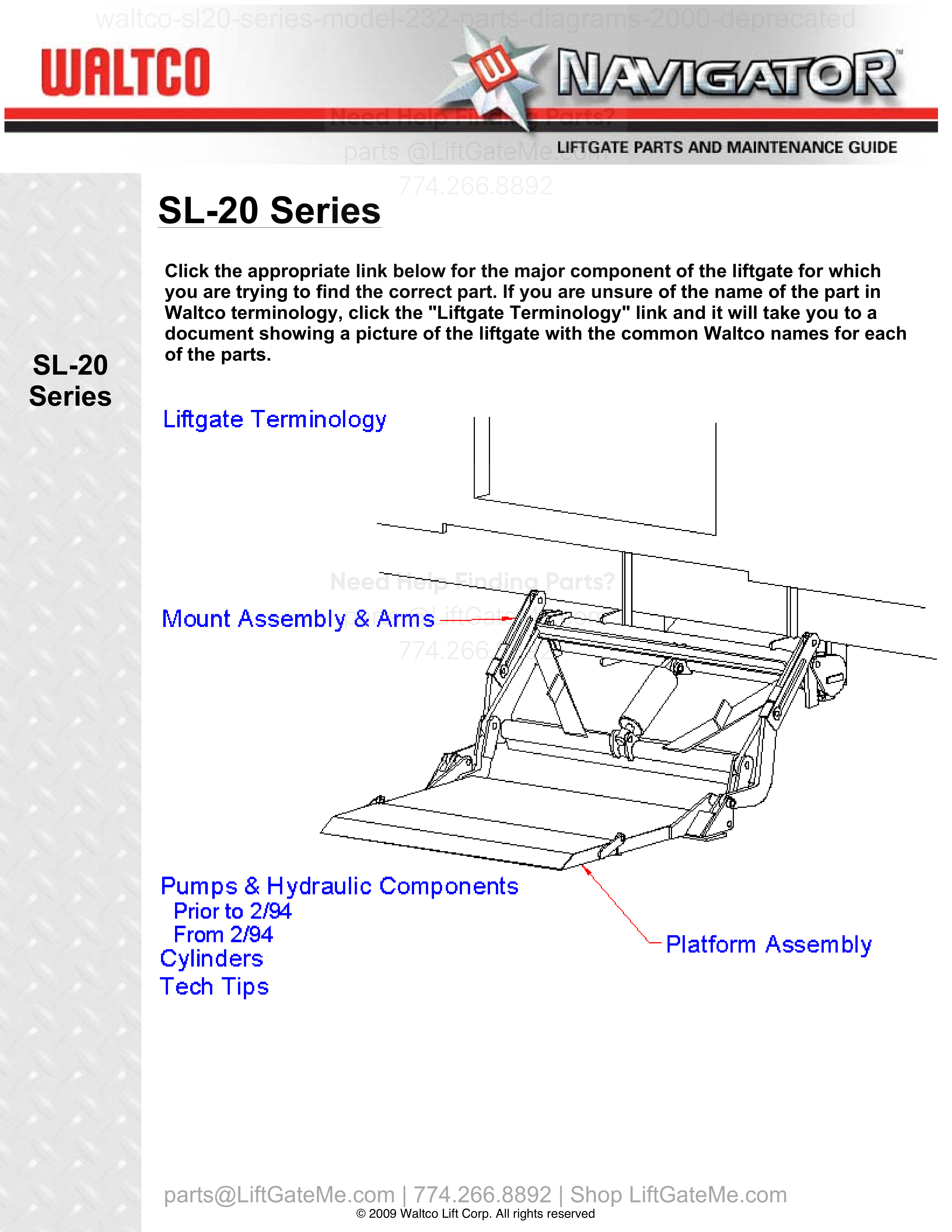
Use this legacy Waltco SL20-Series Model 232 liftgate parts diagram page to identify OEM components, review part callouts, and verify replacement parts for pre-2000 slider-style models.
Compatibility and Purchasing Notice
Although the information on this page is taken from an OEM lift gate manual, if you're unsure whether this data matches your exact model and year, PLEASE contact our team. Part numbers can vary by year - even within the same model - and we're always happy to confirm the correct parts for you.
Have your liftgate serial number ready for faster assistance. Where to find it
i


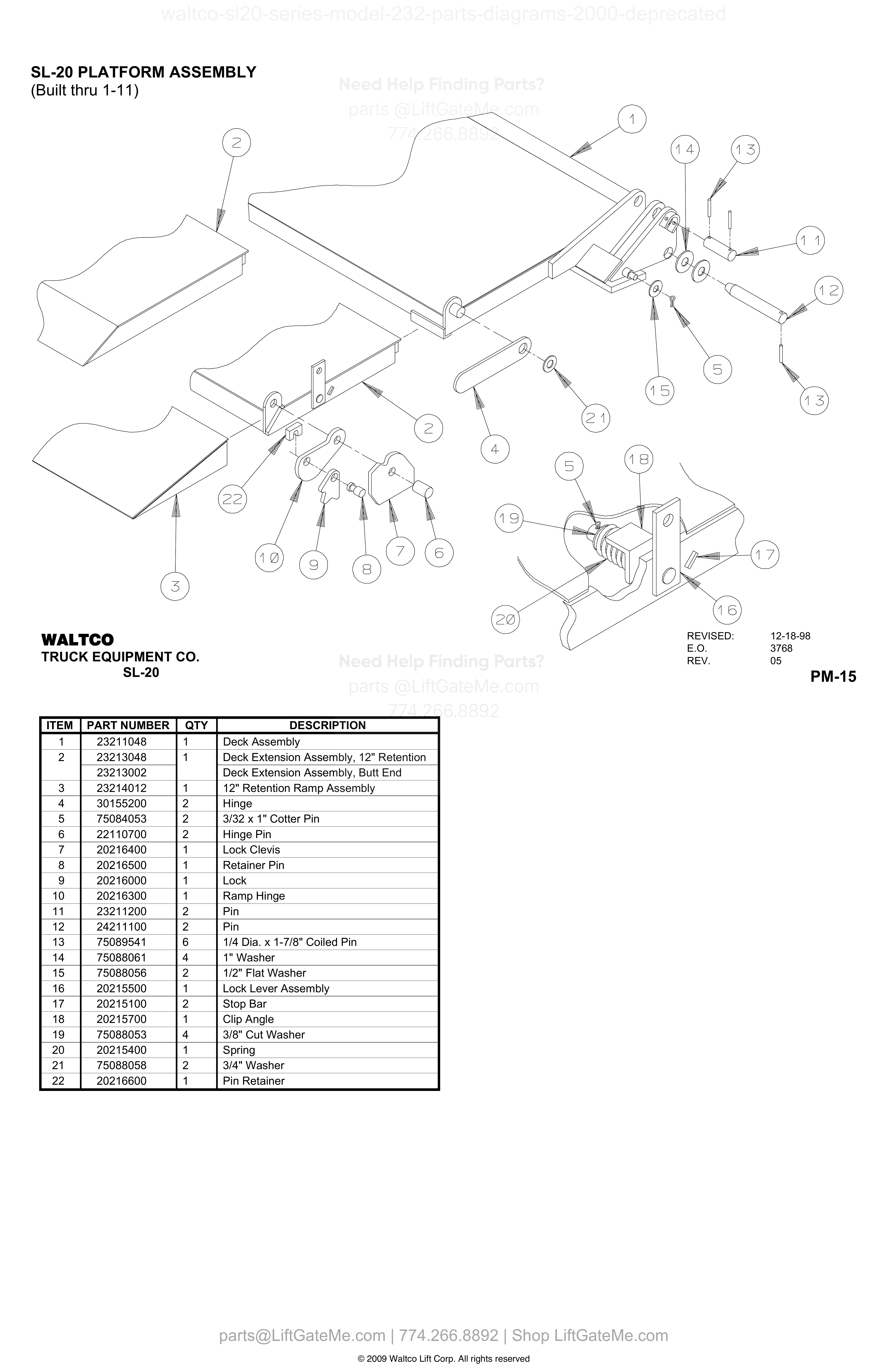
SL-20 PLATFORM ASSEMBLY (Built thru 1-11)
| Item | Qty | Part Number | Description | Actions |
|---|---|---|---|---|
| 1 | 1 | 23211048 | Deck Assembly | |
| 2 | 1 | 23213048 | Deck Extension Assembly, 12" Retention | |
| 2 | 23213002 | Deck Extension Assembly, Butt End | ||
| 3 | 1 | 23214012 | 12" Retention Ramp Assembly | |
| 4 | 2 | 30155200 | Hinge | |
| 5 | 2 | 75084053 | 3/32 x 1" Cotter Pin | |
| 6 | 2 | 22110700 | Hinge Pin | |
| 7 | 1 | 20216400 | Lock Clevis | |
| 8 | 1 | 20216500 | Retainer Pin | |
| 9 | 1 | 20216000 | Lock | |
| 10 | 1 | 20216300 | Ramp Hinge | |
| 11 | 2 | 23211200 | Pin | |
| 12 | 2 | 24211100 | Pin | |
| 13 | 6 | 75089541 | 1/4 Dia. x 1-7/8" Coiled Pin | |
| 14 | 4 | 75088061 | 1" Washer | |
| 15 | 2 | 75088056 | 1/2" Flat Washer | |
| 16 | 1 | 20215500 | Lock Lever Assembly | |
| 17 | 2 | 20215100 | Stop Bar | |
| 18 | 1 | 20215700 | Clip Angle | |
| 19 | 4 | 75088053 | 3/8" Cut Washer | |
| 20 | 1 | 20215400 | Spring | |
| 21 | 2 | 75088058 | 3/4" Washer | |
| 22 | 1 | 20216600 | Pin Retainer |
Reference Notice
Manual links are provided for reference only. If you have any doubt, contact us — we’re happy to verify parts and help you purchase with confidence.
Have your liftgate serial number ready for faster assistance. Where to find it
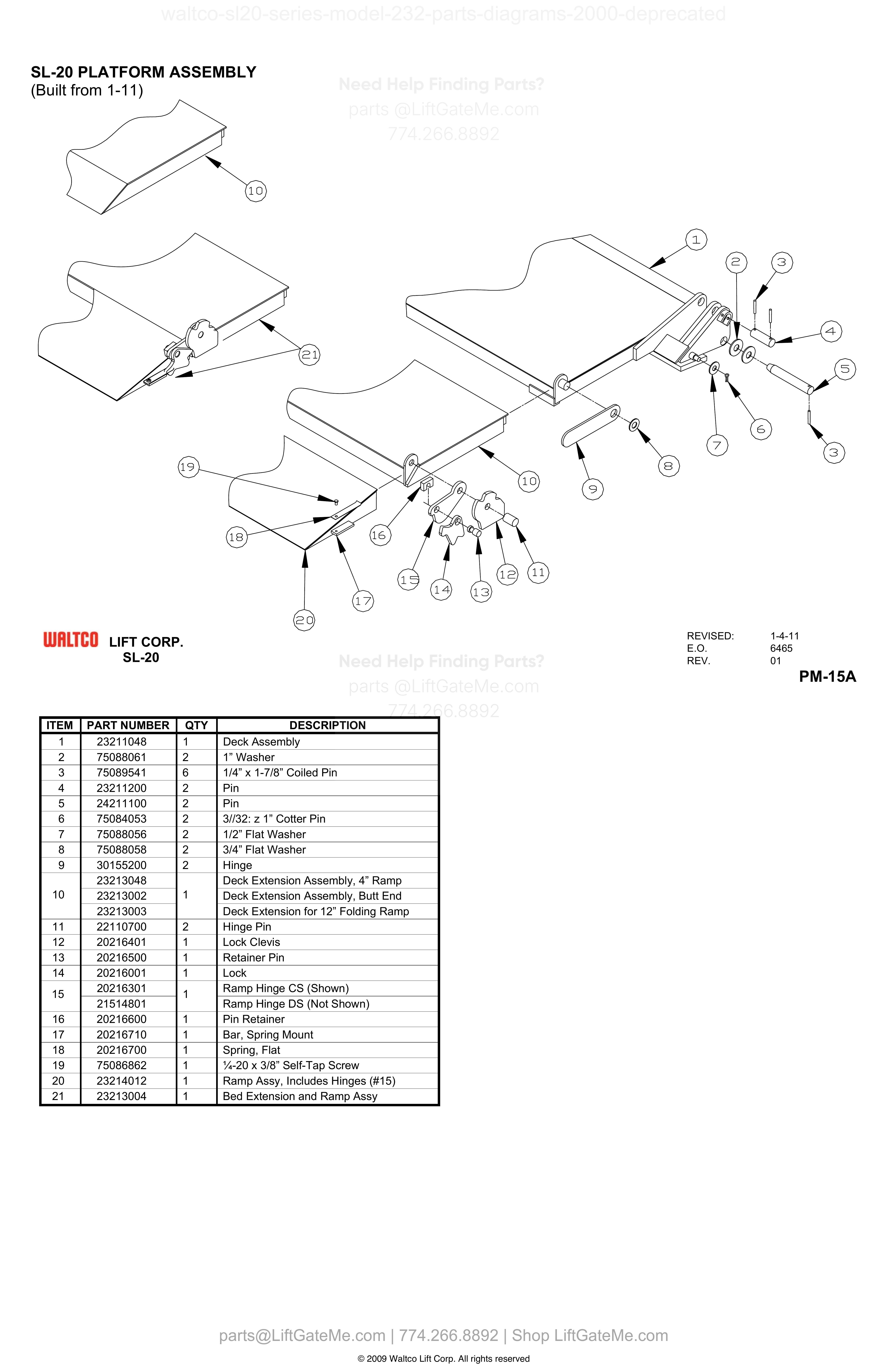
SL-20 PLATFORM ASSEMBLY (Built from 1-11)
| Item | Qty | Part Number | Description | Actions |
|---|---|---|---|---|
| 1 | 1 | 23211048 | Deck Assembly | |
| 2 | 2 | 75088061 | 1” Washer | |
| 3 | 6 | 75089541 | 1/4” x 1-7/8” Coiled Pin | |
| 4 | 2 | 23211200 | Pin | |
| 5 | 2 | 24211100 | Pin | |
| 6 | 2 | 75084053 | 3//32: z 1” Cotter Pin | |
| 7 | 2 | 75088056 | 1/2” Flat Washer | |
| 8 | 2 | 75088058 | 3/4” Flat Washer | |
| 9 | 2 | 30155200 | Hinge | |
| 9 | 23213048 | Deck Extension Assembly, 4” Ramp | ||
| 10 | 1 | 23213002 | Deck Extension Assembly, Butt End | |
| 10 | 23213003 | Deck Extension for 12” Folding Ramp | ||
| 11 | 2 | 22110700 | Hinge Pin | |
| 12 | 1 | 20216401 | Lock Clevis | |
| 13 | 1 | 20216500 | Retainer Pin | |
| 14 | 1 | 20216001 | Lock | |
| 15 | 1 | 20216301 | Ramp Hinge CS (Shown) | |
| 15 | 1 | 21514801 | Ramp Hinge DS (Not Shown) | |
| 16 | 1 | 20216600 | Pin Retainer | |
| 17 | 1 | 20216710 | Bar, Spring Mount | |
| 18 | 1 | 20216700 | Spring, Flat | |
| 19 | 1 | 75086862 | ¼-20 x 3/8” Self-Tap Screw | |
| 20 | 1 | 23214012 | Ramp Assy, Includes Hinges (#15) | |
| 21 | 1 | 23213004 | Bed Extension and Ramp Assy | |
| 10 | 23213048 | Deck Extension Assembly, 4” Ramp |
i

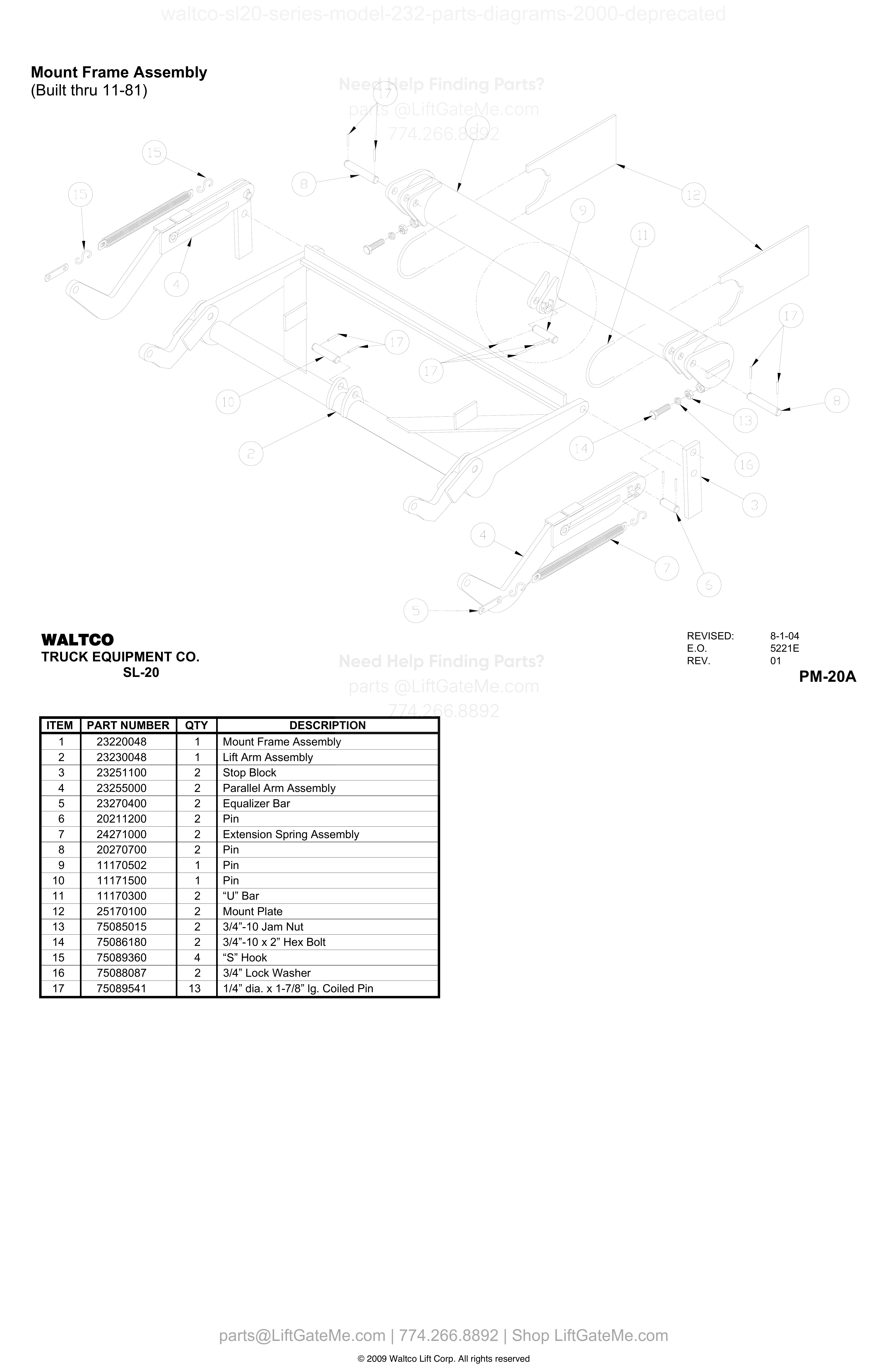
Mount Frame Assembly (Built thru 11-81)
| Item | Qty | Part Number | Description | Actions |
|---|---|---|---|---|
| 1 | 1 | 23220048 | Mount Frame Assembly | |
| 2 | 1 | 23230048 | Lift Arm Assembly | |
| 3 | 2 | 23251100 | Stop Block | |
| 4 | 2 | 23255000 | Parallel Arm Assembly | |
| 5 | 2 | 23270400 | Equalizer Bar | |
| 6 | 2 | 20211200 | Pin | |
| 7 | 2 | 24271000 | Extension Spring Assembly | |
| 8 | 2 | 20270700 | Pin | |
| 9 | 1 | 11170502 | Pin | |
| 10 | 1 | 11171500 | Pin | |
| 11 | 2 | 11170300 | “U” Bar | |
| 12 | 2 | 25170100 | Mount Plate | |
| 13 | 2 | 75085015 | 3/4”-10 Jam Nut | |
| 14 | 2 | 75086180 | 3/4”-10 x 2” Hex Bolt | |
| 15 | 4 | 75089360 | “S” Hook | |
| 16 | 2 | 75088087 | 3/4” Lock Washer | |
| 17 | 13 | 75089541 | 1/4” dia. x 1-7/8” lg. Coiled Pin |
Reference Notice
Manual links are provided for reference only. If you have any doubt, contact us — we’re happy to verify parts and help you purchase with confidence.
Have your liftgate serial number ready for faster assistance. Where to find it
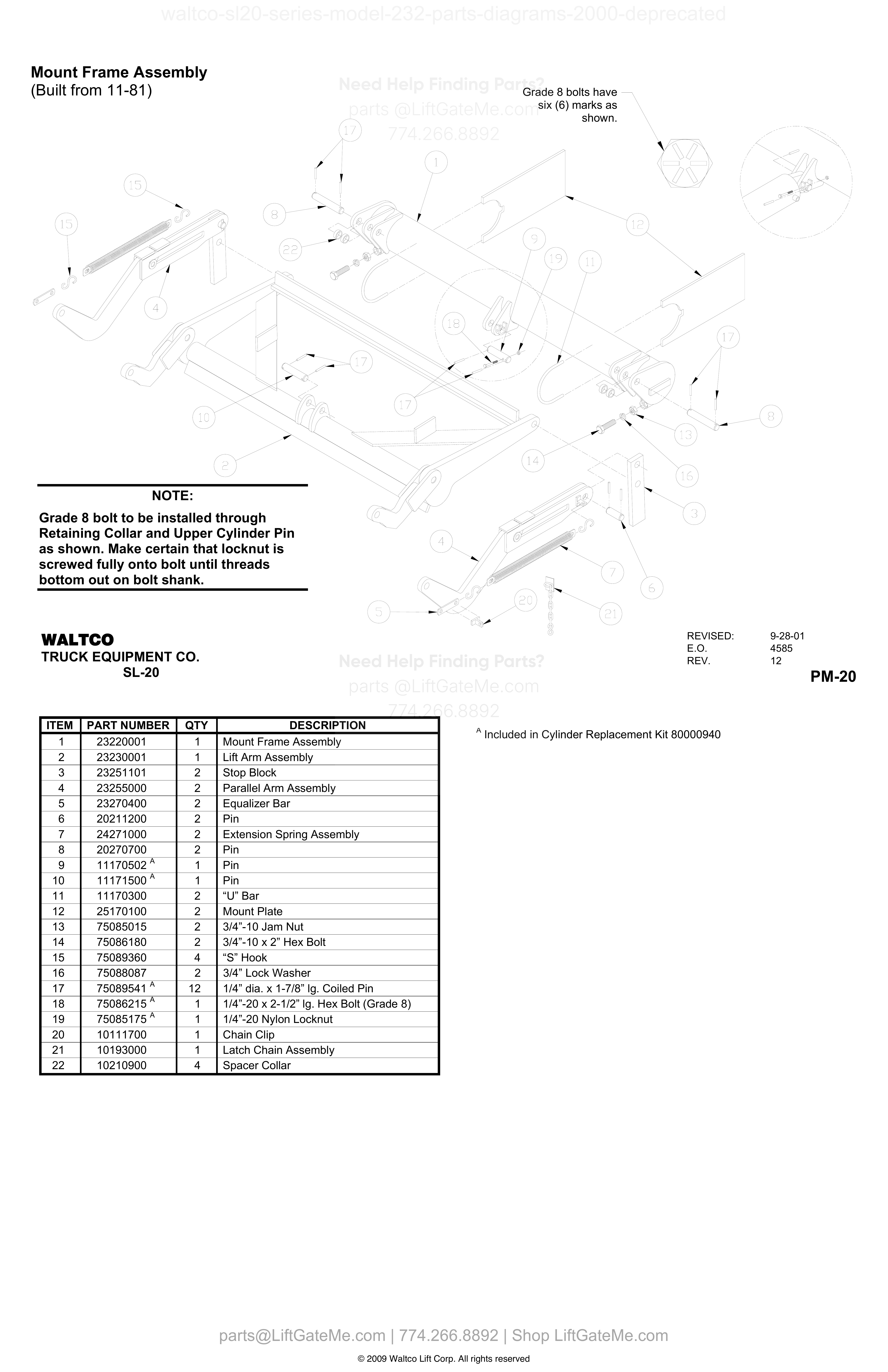
Mount Frame Assembly (Built from 11-81)
| Item | Qty | Part Number | Description | Actions |
|---|---|---|---|---|
| 1 | 1 | 23220001 | Mount Frame Assembly | |
| 2 | 1 | 23230001 | Lift Arm Assembly | |
| 3 | 2 | 23251101 | Stop Block | |
| 4 | 2 | 23255000 | Parallel Arm Assembly | |
| 5 | 2 | 23270400 | Equalizer Bar | |
| 6 | 2 | 20211200 | Pin | |
| 7 | 2 | 24271000 | Extension Spring Assembly | |
| 8 | 2 | 20270700 | Pin | |
| 9 | 1 | 11170502 A | Pin | |
| 10 | 1 | 11171500 A | Pin | |
| 11 | 2 | 11170300 | “U” Bar | |
| 12 | 2 | 25170100 | Mount Plate | |
| 13 | 2 | 75085015 | 3/4”-10 Jam Nut | |
| 14 | 2 | 75086180 | 3/4”-10 x 2” Hex Bolt | |
| 15 | 4 | 75089360 | “S” Hook | |
| 16 | 2 | 75088087 | 3/4” Lock Washer | |
| 17 | 12 | 75089541 A | 1/4” dia. x 1-7/8” lg. Coiled Pin | |
| 18 | 1 | 75086215 A | 1/4”-20 x 2-1/2” lg. Hex Bolt (Grade 8) | |
| 19 | 1 | 75085175 A | 1/4”-20 Nylon Locknut | |
| 20 | 1 | 10111700 | Chain Clip | |
| 21 | 1 | 10193000 | Latch Chain Assembly | |
| 22 | 4 | 10210900 | Spacer Collar |
i


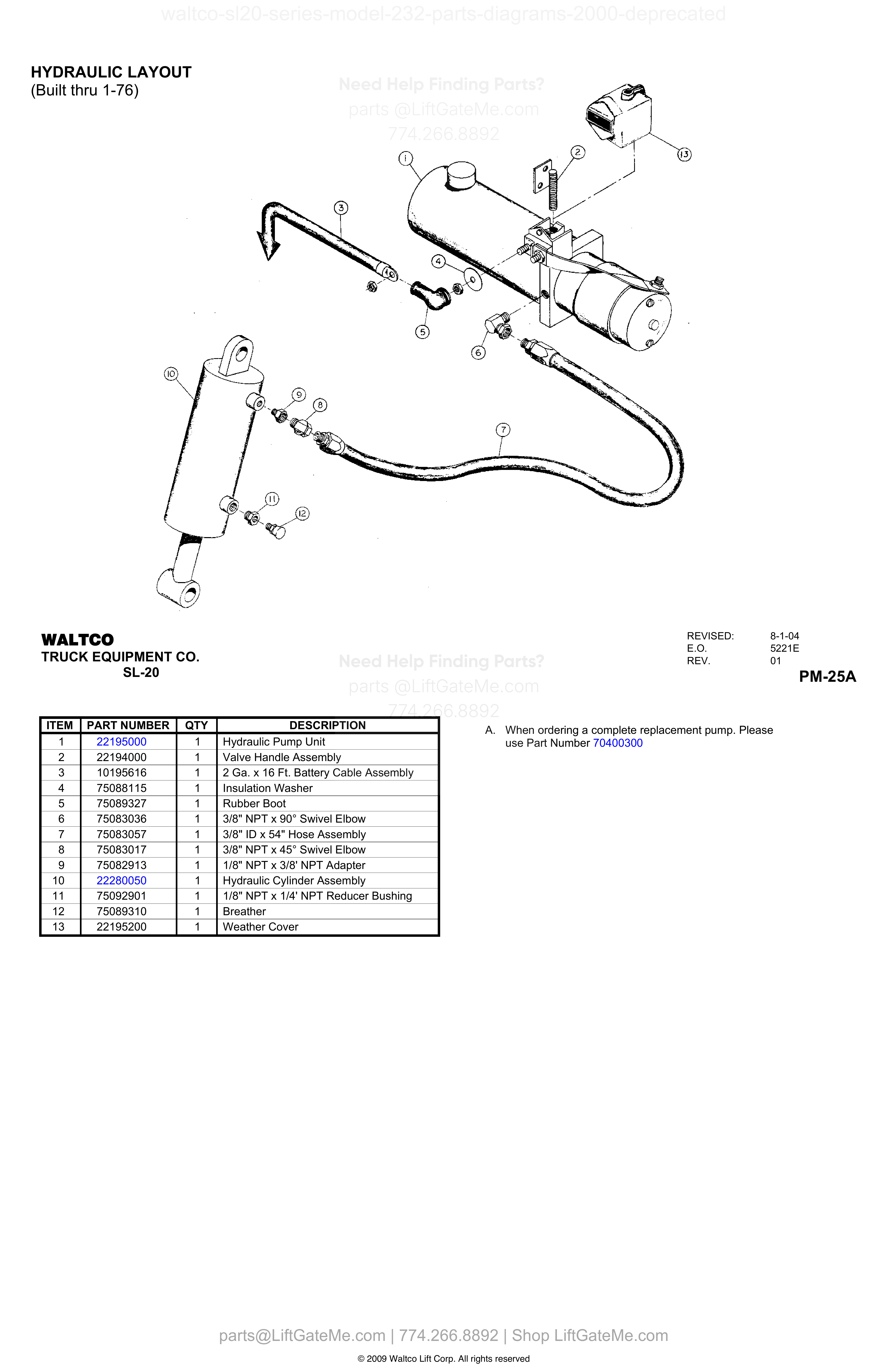
HYDRAULIC LAYOUT
| Item | Qty | Part Number | Description | Actions |
|---|---|---|---|---|
| 1 | 1 | 22195000 | Hydraulic Pump Unit | |
| 2 | 1 | 22194000 | Valve Handle Assembly | |
| 3 | 1 | 10195616 | 2 Ga. x 16 Ft. Battery Cable Assembly | |
| 4 | 1 | 75088115 | Insulation Washer | |
| 5 | 1 | 75089327 | Rubber Boot | |
| 6 | 1 | 75083036 | 3/8" NPT x 90° Swivel Elbow | |
| 7 | 1 | 75083057 | 3/8" ID x 54" Hose Assembly | |
| 8 | 1 | 75083017 | 3/8" NPT x 45° Swivel Elbow | |
| 9 | 1 | 75082913 | 1/8" NPT x 3/8' NPT Adapter | |
| 10 | 1 | 22280050 | Hydraulic Cylinder Assembly | |
| 11 | 1 | 75092901 | 1/8" NPT x 1/4' NPT Reducer Bushing | |
| 12 | 1 | 75089310 | Breather | |
| 13 | 1 | 22195200 | Weather Cover |
Reference Notice
Manual links are provided for reference only. If you have any doubt, contact us — we’re happy to verify parts and help you purchase with confidence.
Have your liftgate serial number ready for faster assistance. Where to find it
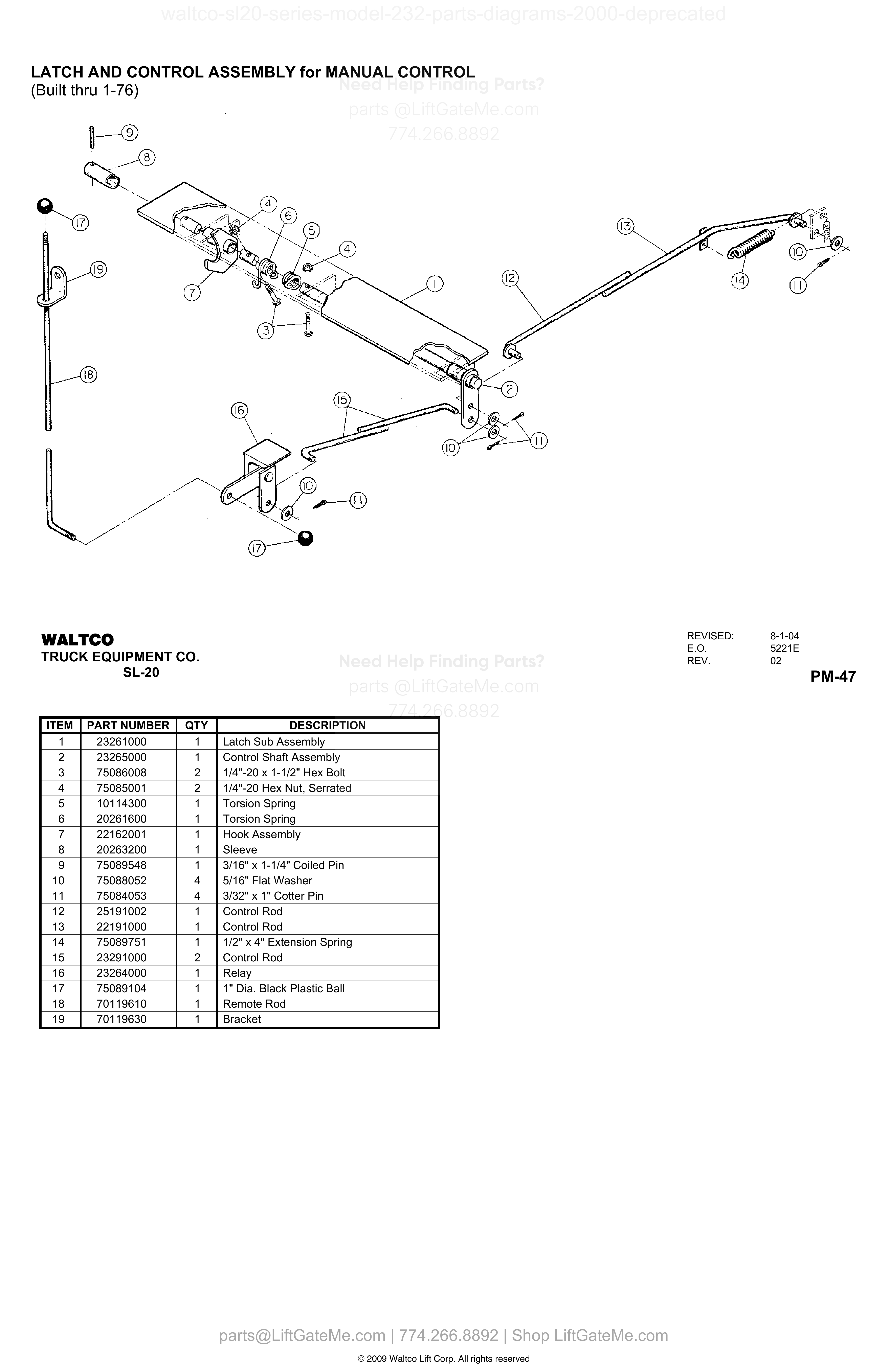
LATCH AND CONTROL ASSEMBLY for MANUAL CONTROL
| Item | Qty | Part Number | Description | Actions |
|---|---|---|---|---|
| 1 | 1 | 23261000 | Latch Sub Assembly | |
| 2 | 1 | 23265000 | Control Shaft Assembly | |
| 3 | 2 | 75086008 | 1/4"-20 x 1-1/2" Hex Bolt | |
| 4 | 2 | 75085001 | 1/4"-20 Hex Nut, Serrated | |
| 5 | 1 | 10114300 | Torsion Spring | |
| 6 | 1 | 20261600 | Torsion Spring | |
| 7 | 1 | 22162001 | Hook Assembly | |
| 8 | 1 | 20263200 | Sleeve | |
| 9 | 1 | 75089548 | 3/16" x 1-1/4" Coiled Pin | |
| 10 | 4 | 75088052 | 5/16" Flat Washer | |
| 11 | 4 | 75084053 | 3/32" x 1" Cotter Pin | |
| 12 | 1 | 25191002 | Control Rod | |
| 13 | 1 | 22191000 | Control Rod | |
| 14 | 1 | 75089751 | 1/2" x 4" Extension Spring | |
| 15 | 2 | 23291000 | Control Rod | |
| 16 | 1 | 23264000 | Relay | |
| 17 | 1 | 75089104 | 1" Dia. Black Plastic Ball | |
| 18 | 1 | 70119610 | Remote Rod | |
| 19 | 1 | 70119630 | Bracket |
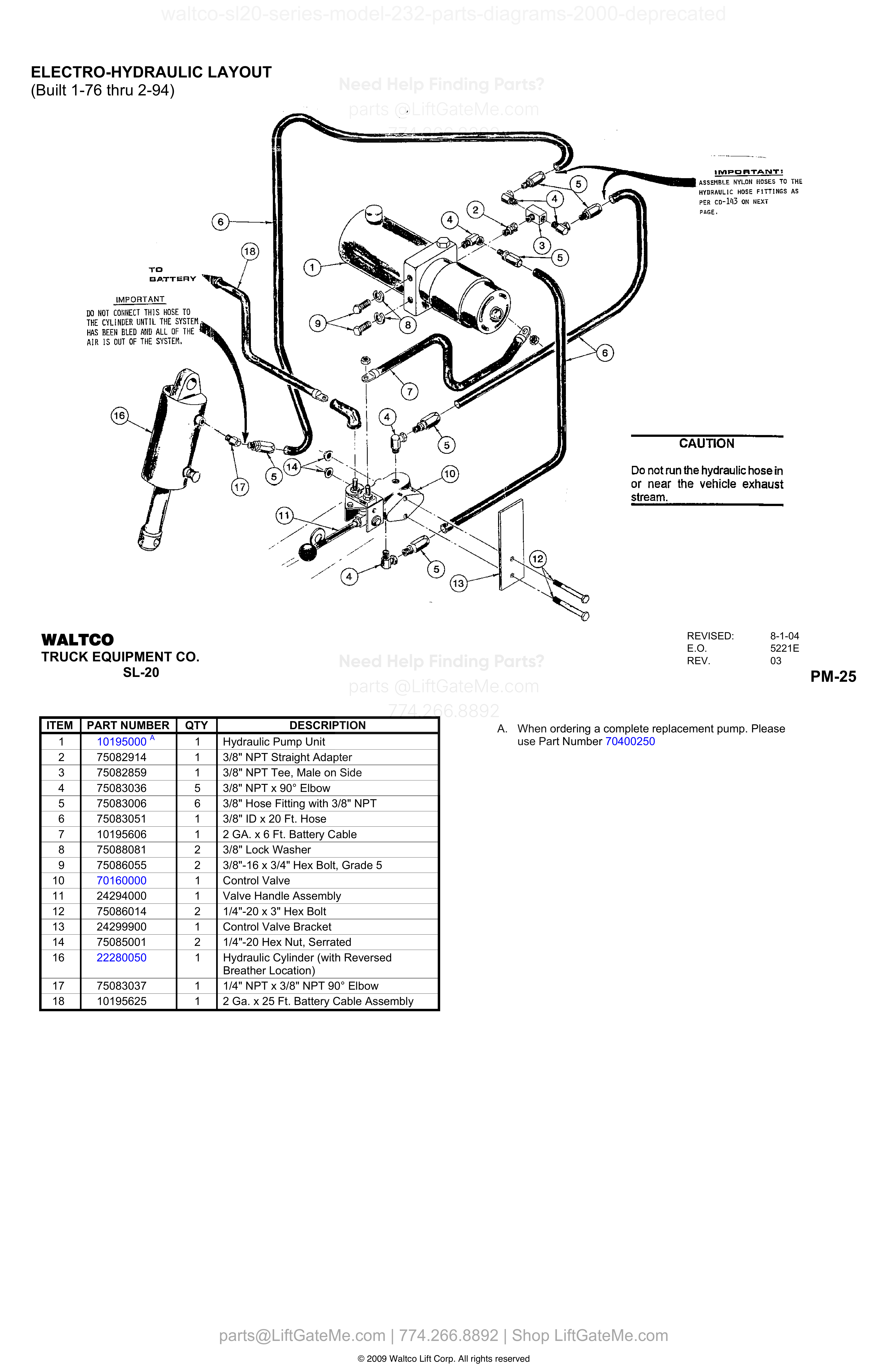
ELECTRO-HYDRAULIC LAYOUT (Built 1-76 thru 2-94)
| Item | Qty | Part Number | Description | Actions |
|---|---|---|---|---|
| 1 | 1 | 10195000 A | Hydraulic Pump Unit | |
| 2 | 1 | 75082914 | 3/8" NPT Straight Adapter | |
| 3 | 1 | 75082859 | 3/8" NPT Tee, Male on Side | |
| 4 | 5 | 75083036 | 3/8" NPT x 90° Elbow | |
| 5 | 6 | 75083006 | 3/8" Hose Fitting with 3/8" NPT | |
| 6 | 1 | 75083051 | 3/8" ID x 20 Ft. Hose | |
| 7 | 1 | 10195606 | 2 GA. x 6 Ft. Battery Cable | |
| 8 | 2 | 75088081 | 3/8" Lock Washer | |
| 9 | 2 | 75086055 | 3/8"-16 x 3/4" Hex Bolt, Grade 5 | |
| 10 | 1 | 70160000 | Control Valve | |
| 11 | 1 | 24294000 | Valve Handle Assembly | |
| 12 | 2 | 75086014 | 1/4"-20 x 3" Hex Bolt | |
| 13 | 1 | 24299900 | Control Valve Bracket | |
| 14 | 2 | 75085001 | 1/4"-20 Hex Nut, Serrated | |
| 16 | 1 | 22280050 | Hydraulic Cylinder (with Reversed Breather Location) | |
| 17 | 1 | 75083037 | 1/4" NPT x 3/8" NPT 90° Elbow | |
| 18 | 1 | 10195625 | 2 Ga. x 25 Ft. Battery Cable Assembly |
Reference Notice
Manual links are provided for reference only. If you have any doubt, contact us — we’re happy to verify parts and help you purchase with confidence.
Have your liftgate serial number ready for faster assistance. Where to find it
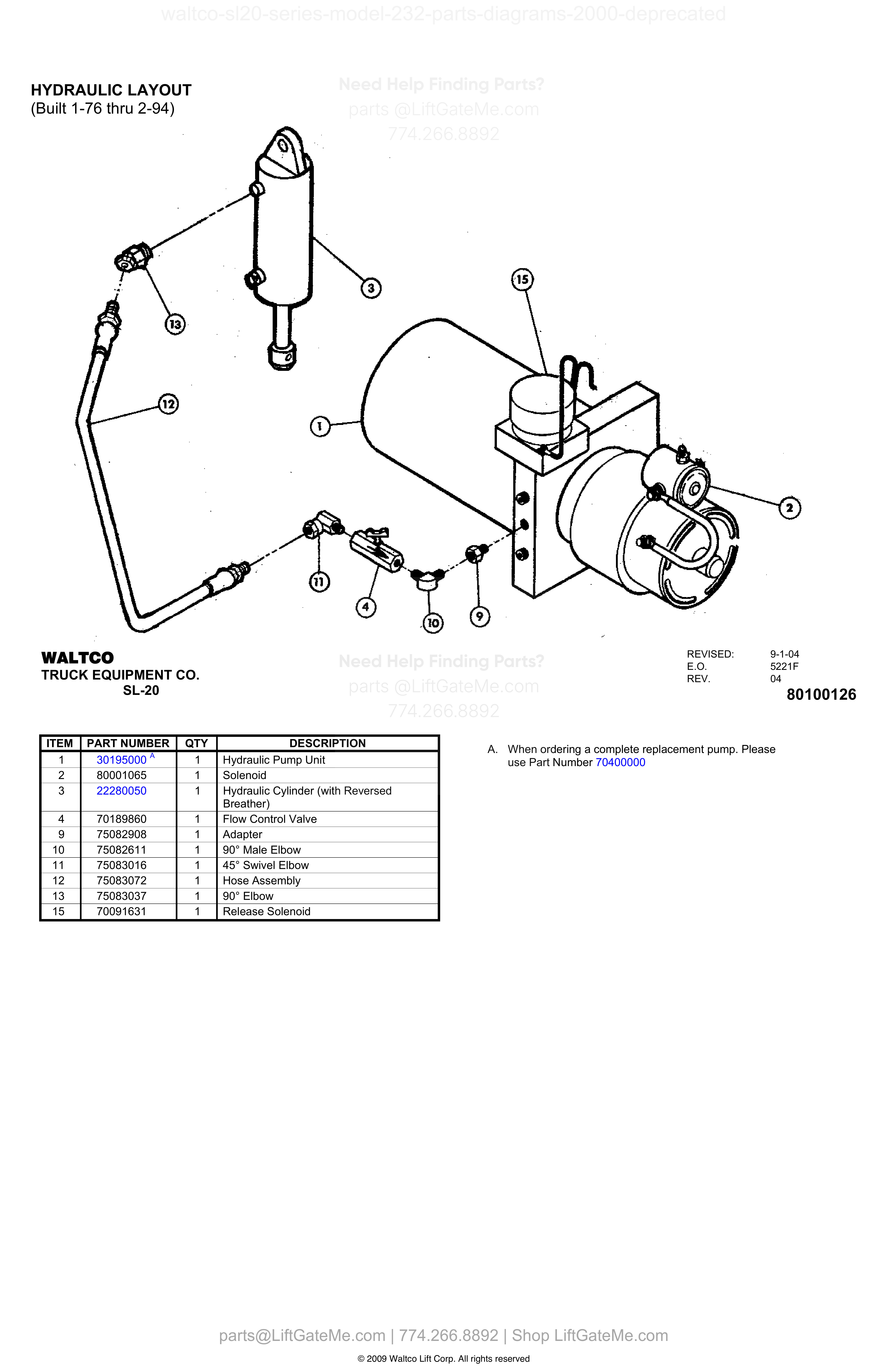
HYDRAULIC LAYOUT
| Item | Qty | Part Number | Description | Actions |
|---|---|---|---|---|
| 1 | 1 | 30195000 A | Hydraulic Pump Unit | |
| 2 | 1 | 80001065 | Solenoid | |
| 3 | 1 | 22280050 | Hydraulic Cylinder (with Reversed Breather) | |
| 4 | 1 | 70189860 | Flow Control Valve | |
| 9 | 1 | 75082908 | Adapter | |
| 10 | 1 | 75082611 | 90° Male Elbow | |
| 11 | 1 | 75083016 | 45° Swivel Elbow | |
| 12 | 1 | 75083072 | Hose Assembly | |
| 13 | 1 | 75083037 | 90° Elbow | |
| 15 | 1 | 70091631 | Release Solenoid |
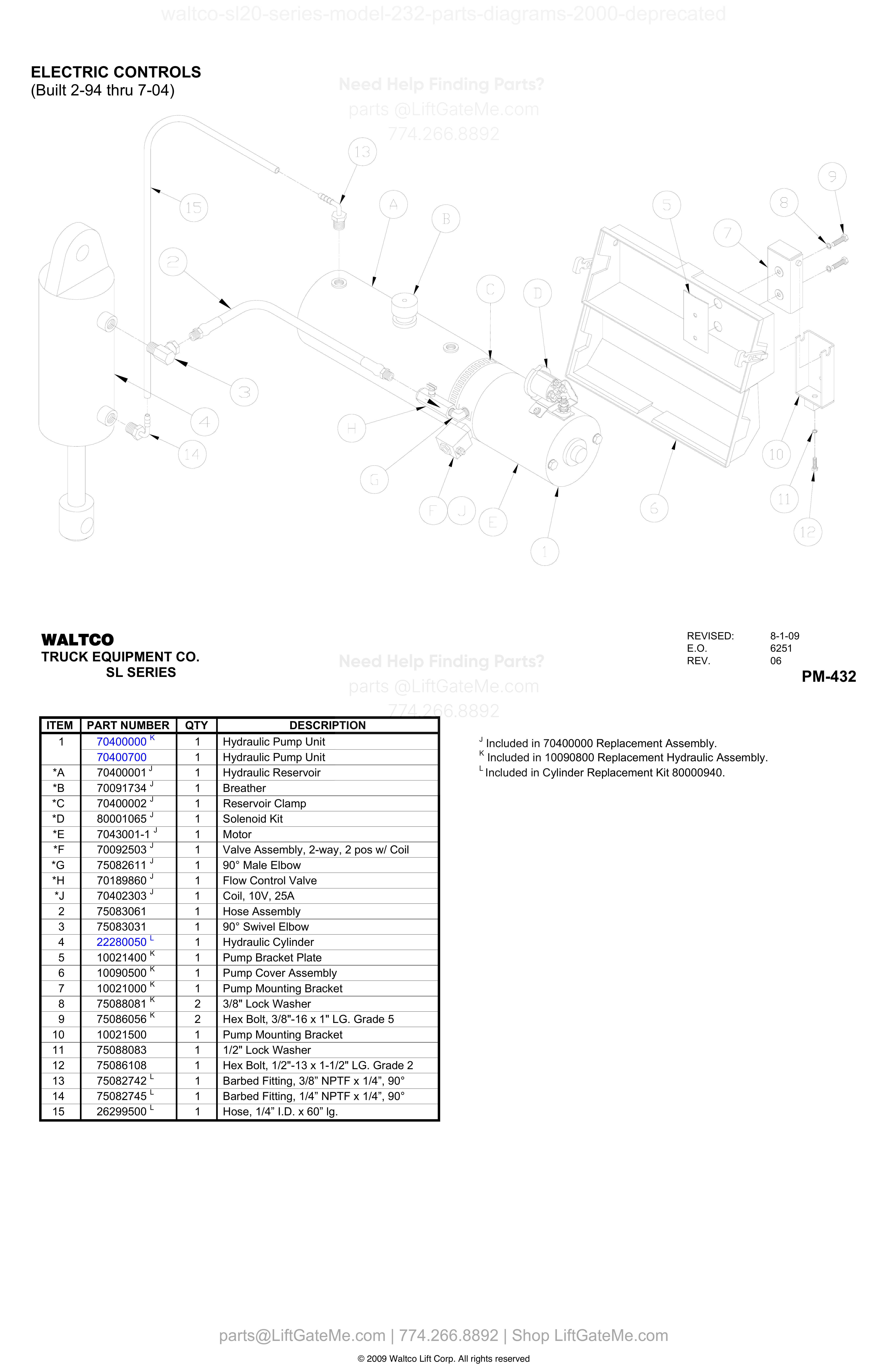
ELECTRIC CONTROLS
| Item | Qty | Part Number | Description | Actions |
|---|---|---|---|---|
| 1 | 1 | 70400000 K | Hydraulic Pump Unit | |
| 1 | 1 | 70400700 | Hydraulic Pump Unit | |
| *A | 1 | 70400001 J | Hydraulic Reservoir | |
| *B | 1 | 70091734 J | Breather | |
| *C | 1 | 70400002 J | Reservoir Clamp | |
| *D | 1 | 80001065 J | Solenoid Kit | |
| *E | 1 | 7043001-1 J | Motor | |
| *F | 1 | 70092503 J | Valve Assembly, 2-way, 2 pos w/ Coil | |
| *G | 1 | 75082611 J | 90° Male Elbow | |
| *H | 1 | 70189860 J | Flow Control Valve | |
| *J | 1 | 70402303 J | Coil, 10V, 25A | |
| 2 | 1 | 75083061 | Hose Assembly | |
| 3 | 1 | 75083031 | 90° Swivel Elbow | |
| 4 | 1 | 22280050 L | Hydraulic Cylinder | |
| 5 | 1 | 10021400 K | Pump Bracket Plate | |
| 6 | 1 | 10090500 K | Pump Cover Assembly | |
| 7 | 1 | 10021000 K | Pump Mounting Bracket | |
| 8 | 2 | 75088081 K | 3/8" Lock Washer | |
| 9 | 2 | 75086056 K | Hex Bolt, 3/8"-16 x 1" LG. Grade 5 | |
| 10 | 1 | 10021500 | Pump Mounting Bracket | |
| 11 | 1 | 75088083 | 1/2" Lock Washer | |
| 12 | 1 | 75086108 | Hex Bolt, 1/2"-13 x 1-1/2" LG. Grade 2 | |
| 13 | 1 | 75082742 L | Barbed Fitting, 3/8” NPTF x 1/4”, 90° | |
| 14 | 1 | 75082745 L | Barbed Fitting, 1/4” NPTF x 1/4”, 90° | |
| 15 | 1 | 26299500 L | Hose, 1/4” I.D. x 60” lg. |
Reference Notice
Manual links are provided for reference only. If you have any doubt, contact us — we’re happy to verify parts and help you purchase with confidence.
Have your liftgate serial number ready for faster assistance. Where to find it
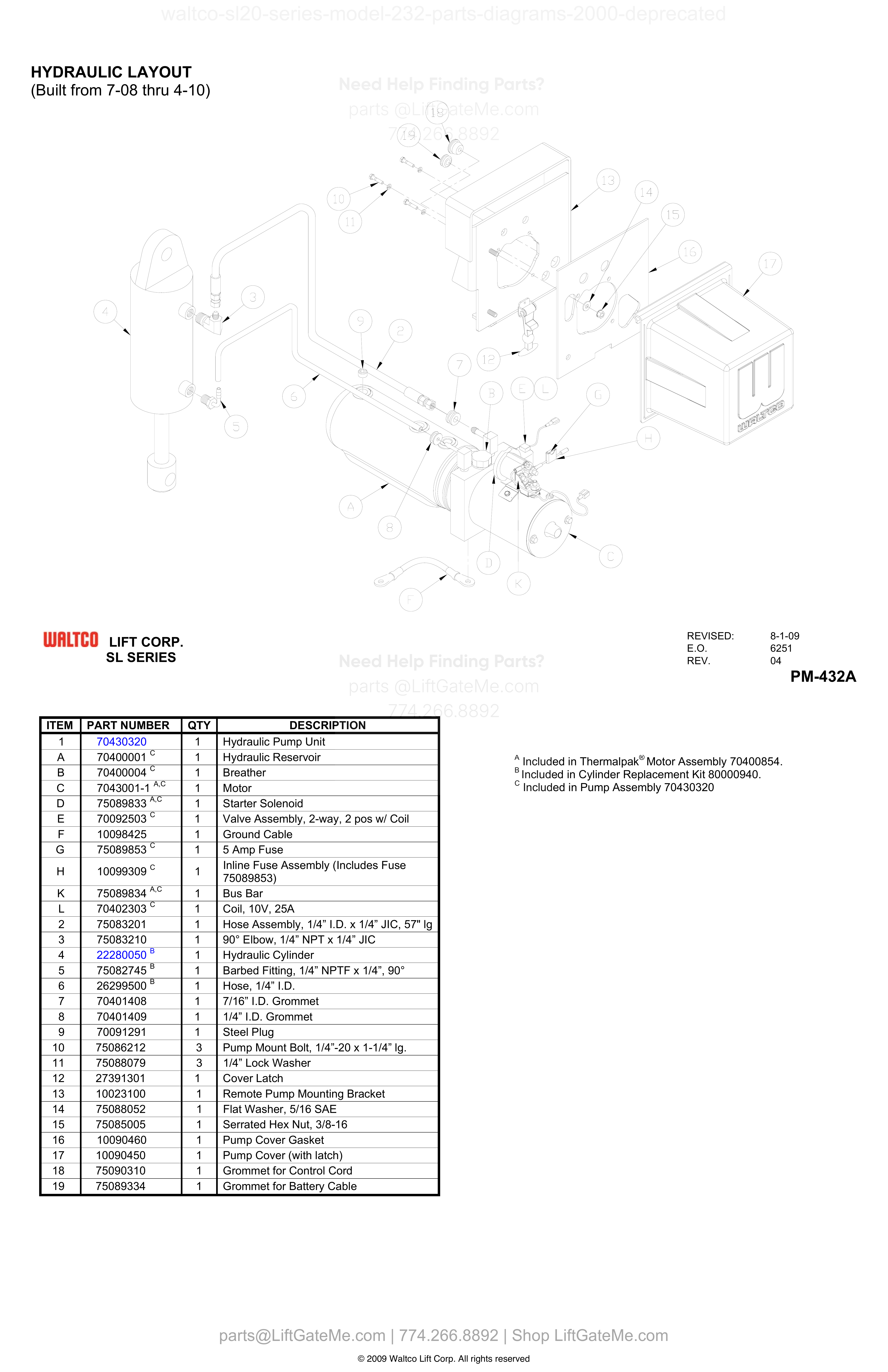
HYDRAULIC LAYOUT
| Item | Qty | Part Number | Description | Actions |
|---|---|---|---|---|
| 1 | 1 | 70430320 | Hydraulic Pump Unit | |
| A | 1 | 70400001 C | Hydraulic Reservoir | |
| B | 1 | 70400004 C | Breather | |
| C | 1 | 7043001-1 A,C | Motor | |
| D | 1 | 75089833 A,C | Starter Solenoid | |
| E | 1 | 70092503 C | Valve Assembly, 2-way, 2 pos w/ Coil | |
| F | 1 | 10098425 | Ground Cable | |
| G | 1 | 75089853 C | 5 Amp Fuse | |
| H | 1 | 10099309 C | Inline Fuse Assembly (Includes Fuse 75089853) | |
| K | 1 | 75089834 A,C | Bus Bar | |
| L | 1 | 70402303 C | Coil, 10V, 25A | |
| 2 | 1 | 75083201 | Hose Assembly, 1/4” I.D. x 1/4” JIC, 57" lg | |
| 3 | 1 | 75083210 | 90° Elbow, 1/4” NPT x 1/4” JIC | |
| 4 | 1 | 22280050 B | Hydraulic Cylinder | |
| 5 | 1 | 75082745 B | Barbed Fitting, 1/4” NPTF x 1/4”, 90° | |
| 6 | 1 | 26299500 B | Hose, 1/4” I.D. | |
| 7 | 1 | 70401408 | 7/16” I.D. Grommet | |
| 8 | 1 | 70401409 | 1/4” I.D. Grommet | |
| 9 | 1 | 70091291 | Steel Plug | |
| 10 | 3 | 75086212 | Pump Mount Bolt, 1/4”-20 x 1-1/4” lg. | |
| 11 | 3 | 75088079 | 1/4” Lock Washer | |
| 12 | 1 | 27391301 | Cover Latch | |
| 13 | 1 | 10023100 | Remote Pump Mounting Bracket | |
| 14 | 1 | 75088052 | Flat Washer, 5/16 SAE | |
| 15 | 1 | 75085005 | Serrated Hex Nut, 3/8-16 | |
| 16 | 1 | 10090460 | Pump Cover Gasket | |
| 17 | 1 | 10090450 | Pump Cover (with latch) | |
| 18 | 1 | 75090310 | Grommet for Control Cord | |
| 19 | 1 | 75089334 | Grommet for Battery Cable |
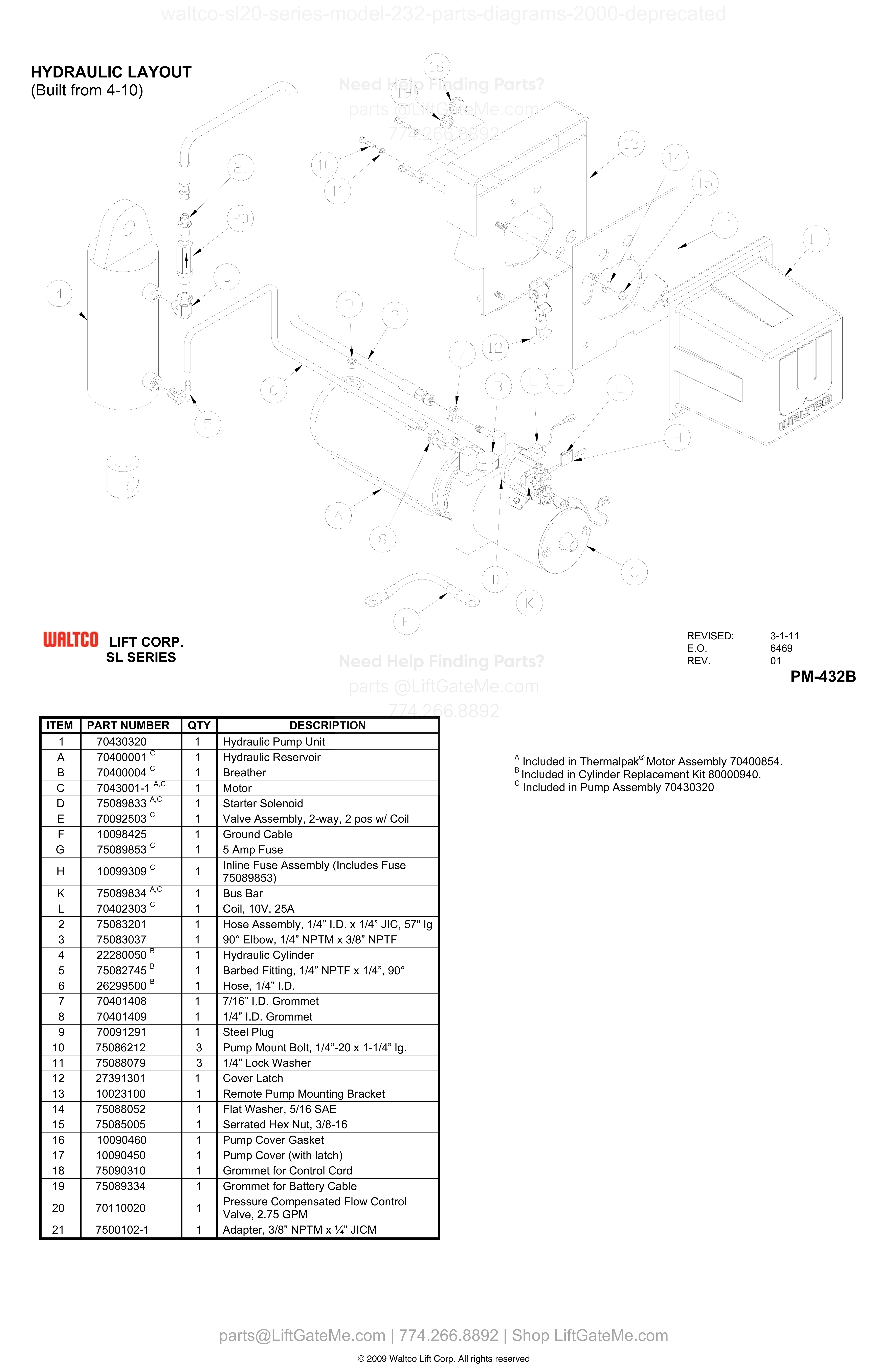
HYDRAULIC LAYOUT (Built from 4-10)
| Item | Qty | Part Number | Description | Actions |
|---|---|---|---|---|
| 1 | 1 | 70430320 | Hydraulic Pump Unit | |
| A | 1 | 70400001 C | Hydraulic Reservoir | |
| B | 1 | 70400004 C | Breather | |
| C | 1 | 7043001-1 A,C | Motor | |
| D | 1 | 75089833 A,C | Starter Solenoid | |
| E | 1 | 70092503 C | Valve Assembly, 2-way, 2 pos w/ Coil | |
| F | 1 | 10098425 | Ground Cable | |
| G | 1 | 75089853 C | 5 Amp Fuse | |
| H | 1 | 10099309 C | Inline Fuse Assembly (Includes Fuse 75089853) | |
| K | 1 | 75089834 A,C | Bus Bar | |
| L | 1 | 70402303 C | Coil, 10V, 25A | |
| 2 | 1 | 75083201 | Hose Assembly, 1/4” I.D. x 1/4” JIC, 57" lg | |
| 3 | 1 | 75083037 | 90° Elbow, 1/4” NPTM x 3/8” NPTF | |
| 4 | 1 | 22280050 B | Hydraulic Cylinder | |
| 5 | 1 | 75082745 B | Barbed Fitting, 1/4” NPTF x 1/4”, 90° | |
| 6 | 1 | 26299500 B | Hose, 1/4” I.D. | |
| 7 | 1 | 70401408 | 7/16” I.D. Grommet | |
| 8 | 1 | 70401409 | 1/4” I.D. Grommet | |
| 9 | 1 | 70091291 | Steel Plug | |
| 10 | 3 | 75086212 | Pump Mount Bolt, 1/4”-20 x 1-1/4” lg. | |
| 11 | 3 | 75088079 | 1/4” Lock Washer | |
| 12 | 1 | 27391301 | Cover Latch | |
| 13 | 1 | 10023100 | Remote Pump Mounting Bracket | |
| 14 | 1 | 75088052 | Flat Washer, 5/16 SAE | |
| 15 | 1 | 75085005 | Serrated Hex Nut, 3/8-16 | |
| 16 | 1 | 10090460 | Pump Cover Gasket | |
| 17 | 1 | 10090450 | Pump Cover (with latch) | |
| 18 | 1 | 75090310 | Grommet for Control Cord | |
| 19 | 1 | 75089334 | Grommet for Battery Cable | |
| 20 | 1 | 70110020 | Pressure Compensated Flow Control Valve, 2.75 GPM | |
| 21 | 1 | 7500102-1 | Adapter, 3/8” NPTM x ¼” JICM |
Reference Notice
Manual links are provided for reference only. If you have any doubt, contact us — we’re happy to verify parts and help you purchase with confidence.
Have your liftgate serial number ready for faster assistance. Where to find it
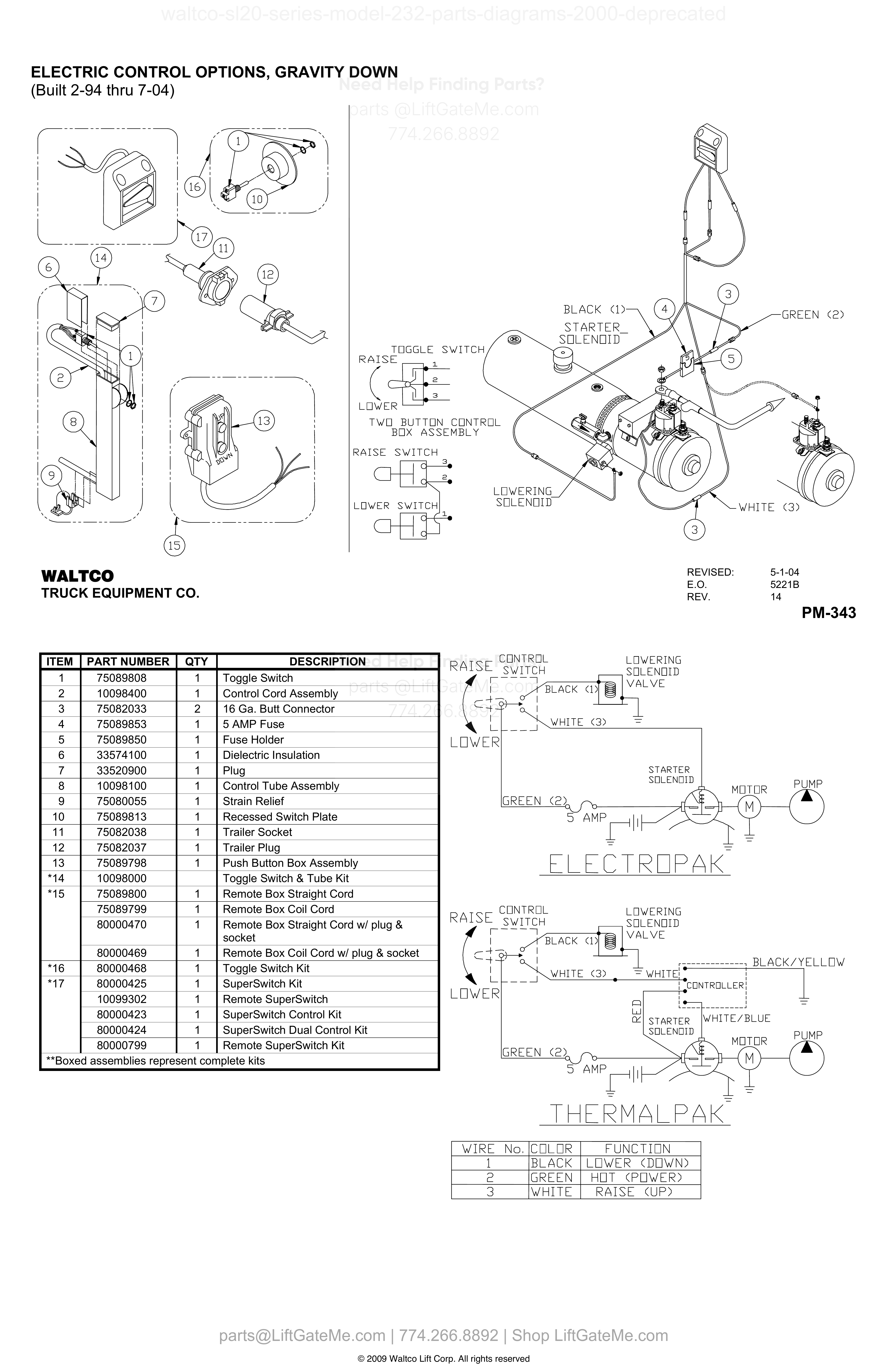
ELECTRIC CONTROL OPTIONS, GRAVITY DOWN
| Item | Qty | Part Number | Description | Actions |
|---|---|---|---|---|
| 1 | 1 | 75089808 | Toggle Switch | |
| 2 | 1 | 10098400 | Control Cord Assembly | |
| 3 | 2 | 75082033 | 16 Ga. Butt Connector | |
| 4 | 1 | 75089853 | 5 AMP Fuse | |
| 5 | 1 | 75089850 | Fuse Holder | |
| 6 | 1 | 33574100 | Dielectric Insulation | |
| 7 | 1 | 33520900 | Plug | |
| 8 | 1 | 10098100 | Control Tube Assembly | |
| 9 | 1 | 75080055 | Strain Relief | |
| 10 | 1 | 75089813 | Recessed Switch Plate | |
| 11 | 1 | 75082038 | Trailer Socket | |
| 12 | 1 | 75082037 | Trailer Plug | |
| 13 | 1 | 75089798 | Push Button Box Assembly | |
| *14 | 10098000 | Toggle Switch & Tube Kit | ||
| *15 | 1 | 75089800 | Remote Box Straight Cord | |
| *15 | 1 | 75089799 | Remote Box Coil Cord | |
| *15 | 1 | 80000470 | Remote Box Straight Cord w/ plug & socket | |
| *15 | 1 | 80000469 | Remote Box Coil Cord w/ plug & socket | |
| *16 | 1 | 80000468 | Toggle Switch Kit | |
| *17 | 1 | 80000425 | SuperSwitch Kit | |
| *17 | 1 | 10099302 | Remote SuperSwitch | |
| *17 | 1 | 80000423 | SuperSwitch Control Kit | |
| *17 | 1 | 80000424 | SuperSwitch Dual Control Kit | |
| *17 | 1 | 80000799 | Remote SuperSwitch Kit |
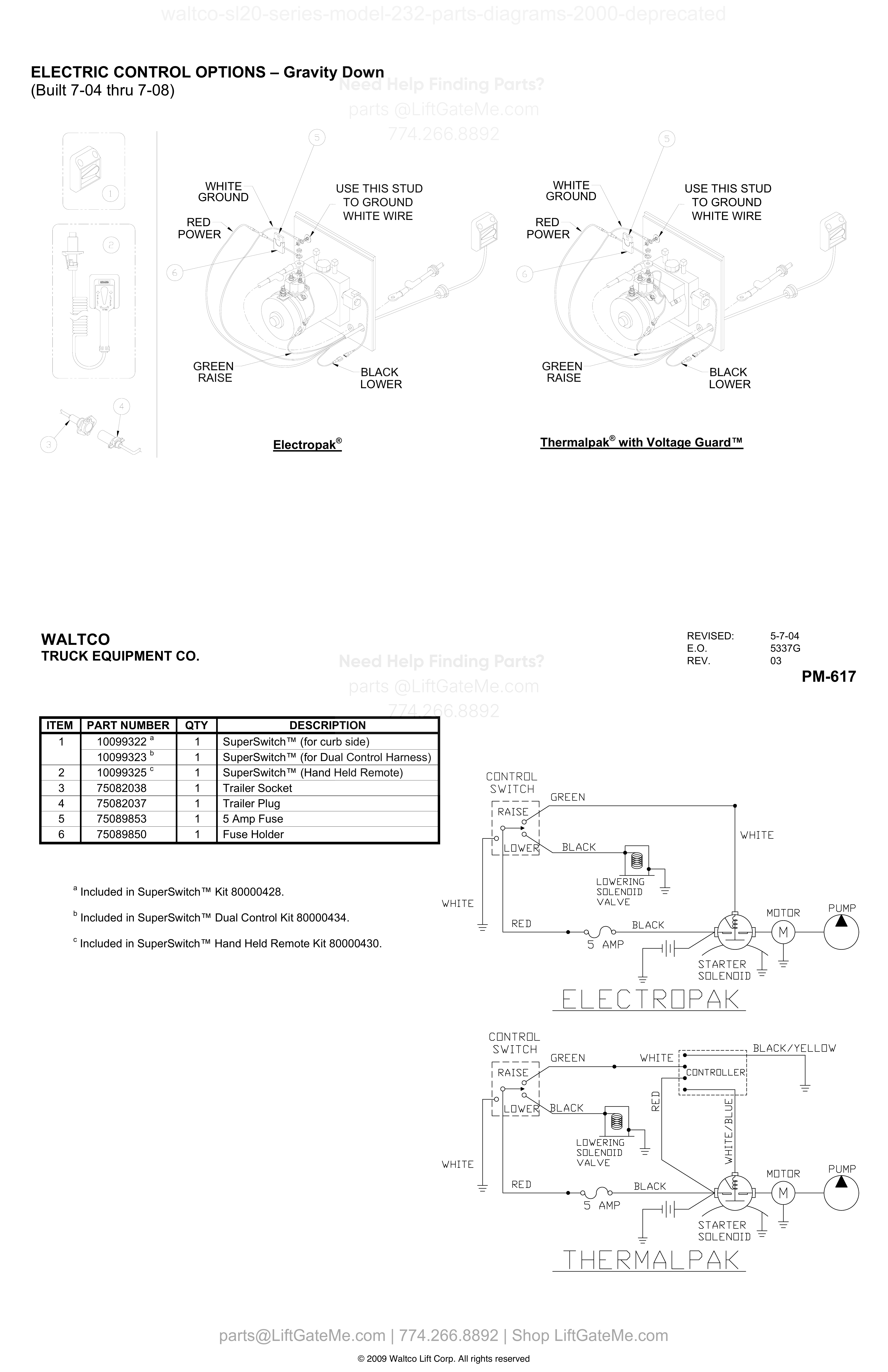
ELECTRIC CONTROL OPTIONS – Gravity Down (Built 7-04 thru 7-08)
| Item | Qty | Part Number | Description | Actions |
|---|---|---|---|---|
| 1 | 1 | 10099322 A | SuperSwitch™ (for curb side) | |
| 1 | 1 | 10099323 B | SuperSwitch™ (for Dual Control Harness) | |
| 2 | 1 | 10099325 C | SuperSwitch™ (Hand Held Remote) | |
| 3 | 1 | 75082038 | Trailer Socket | |
| 4 | 1 | 75082037 | Trailer Plug | |
| 5 | 1 | 75089853 | 5 Amp Fuse | |
| 6 | 1 | 75089850 | Fuse Holder |
Reference Notice
Manual links are provided for reference only. If you have any doubt, contact us — we’re happy to verify parts and help you purchase with confidence.
Have your liftgate serial number ready for faster assistance. Where to find it
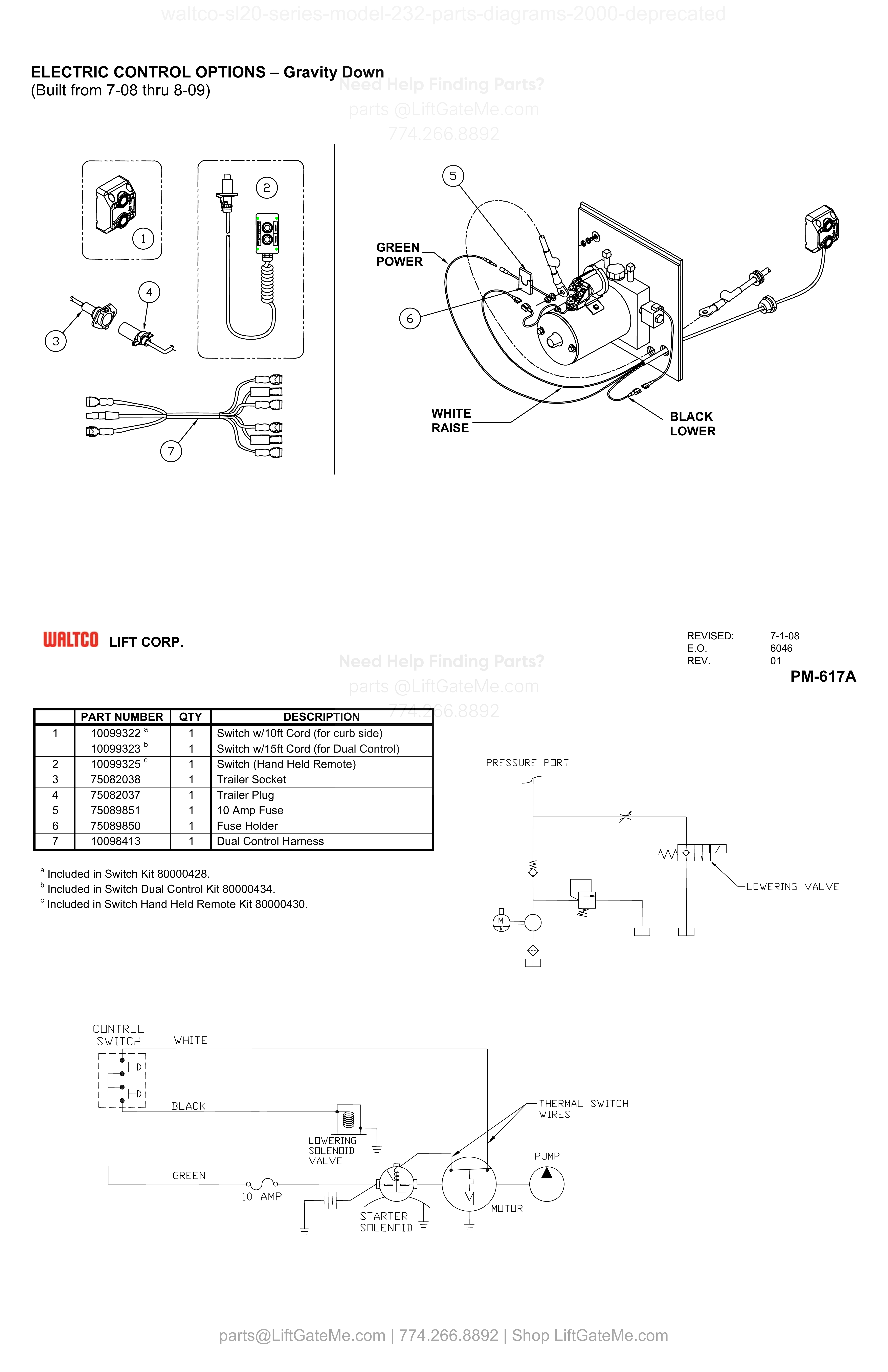
ELECTRIC CONTROL OPTIONS – Gravity Down (Built from 7-08 thru 8-09)
| Item | Qty | Part Number | Description | Actions |
|---|---|---|---|---|
| 1 | 1 | 10099322 A | Switch w/10ft Cord (for curb side) | |
| 1 | 1 | 10099323 B | Switch w/15ft Cord (for Dual Control) | |
| 2 | 1 | 10099325 C | Switch (Hand Held Remote) | |
| 3 | 1 | 75082038 | Trailer Socket | |
| 4 | 1 | 75082037 | Trailer Plug | |
| 5 | 1 | 75089851 | 10 Amp Fuse | |
| 6 | 1 | 75089850 | Fuse Holder | |
| 7 | 1 | 10098413 | Dual Control Harness |
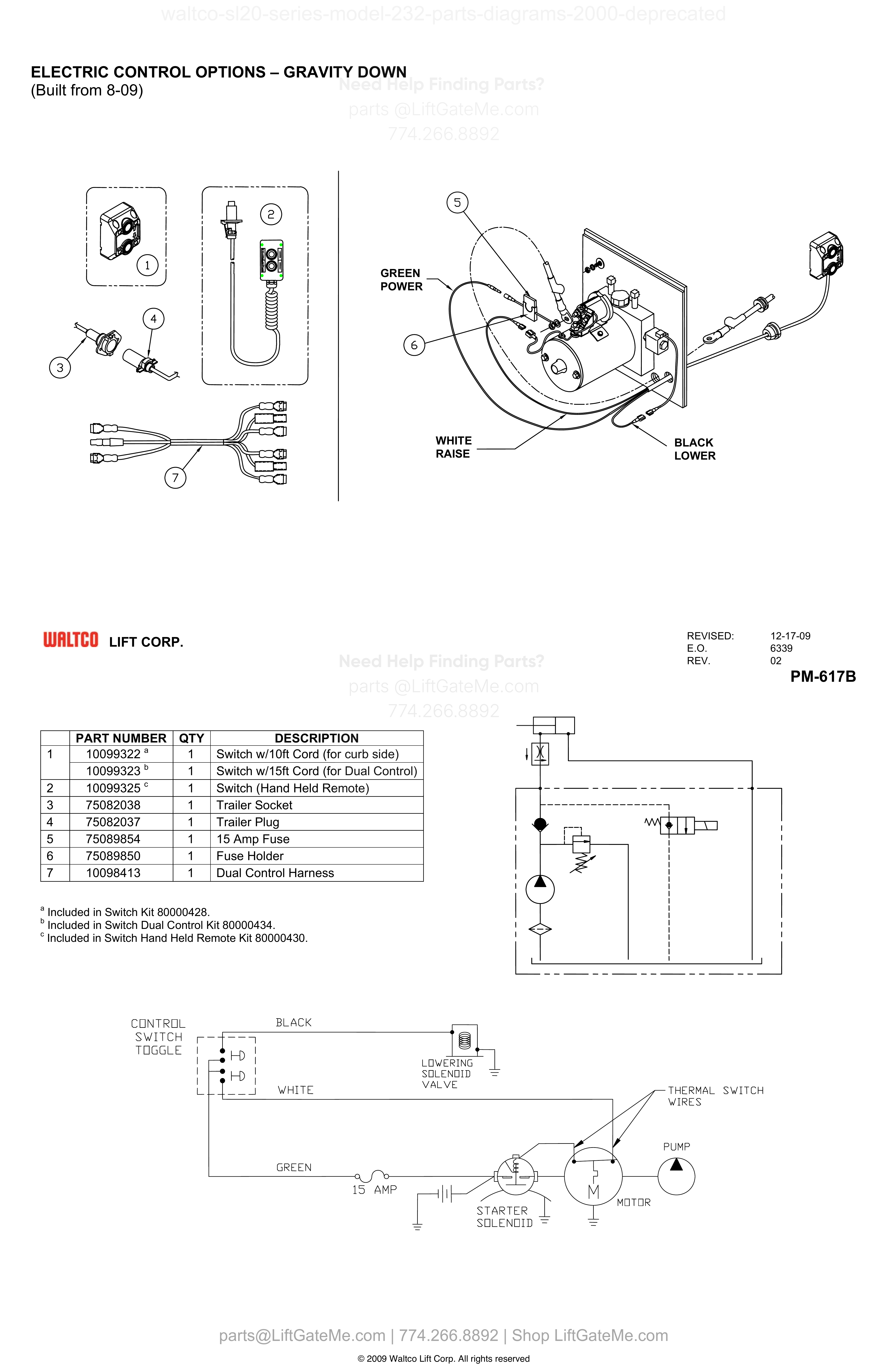
ELECTRIC CONTROL OPTIONS – GRAVITY DOWN (Built from 8-09)
| Item | Qty | Part Number | Description | Actions |
|---|---|---|---|---|
| 1 | 1 | 10099322 A | Switch w/10ft Cord (for curb side) | |
| 1 | 1 | 10099323 B | Switch w/15ft Cord (for Dual Control) | |
| 2 | 1 | 10099325 C | Switch (Hand Held Remote) | |
| 3 | 1 | 75082038 | Trailer Socket | |
| 4 | 1 | 75082037 | Trailer Plug | |
| 5 | 1 | 75089854 | 15 Amp Fuse | |
| 6 | 1 | 75089850 | Fuse Holder | |
| 7 | 1 | 10098413 | Dual Control Harness |
Reference Notice
Manual links are provided for reference only. If you have any doubt, contact us — we’re happy to verify parts and help you purchase with confidence.
Have your liftgate serial number ready for faster assistance. Where to find it
i

SOLENOID OPERATED PUMP UNIT
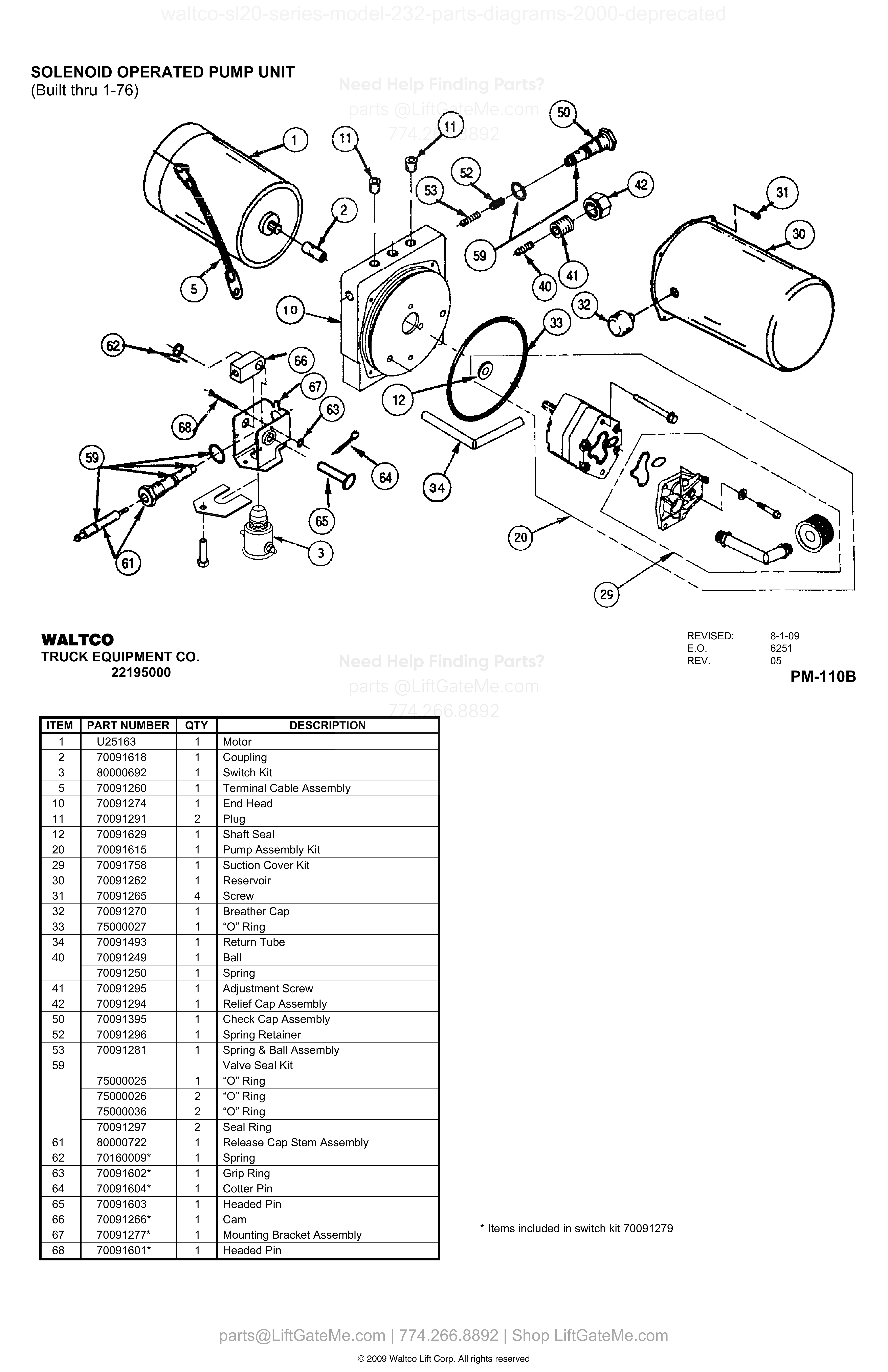
| Item | Qty | Part Number | Description | Actions |
|---|---|---|---|---|
| 1 | 1 | U25163 | Motor | |
| 2 | 1 | 70091618 | Coupling | |
| 3 | 1 | 80000692 | Switch Kit | |
| 5 | 1 | 70091260 | Terminal Cable Assembly | |
| 10 | 1 | 70091274 | End Head | |
| 11 | 2 | 70091291 | Plug | |
| 12 | 1 | 70091629 | Shaft Seal | |
| 20 | 1 | 70091615 | Pump Assembly Kit | |
| 29 | 1 | 70091758 | Suction Cover Kit | |
| 30 | 1 | 70091262 | Reservoir | |
| 31 | 4 | 70091265 | Screw | |
| 32 | 1 | 70091270 | Breather Cap | |
| 33 | 1 | 75000027 | “O” Ring | |
| 34 | 1 | 70091493 | Return Tube | |
| 40 | 1 | 70091249 | Ball | |
| 40 | 1 | 70091250 | Spring | |
| 41 | 1 | 70091295 | Adjustment Screw | |
| 42 | 1 | 70091294 | Relief Cap Assembly | |
| 50 | 1 | 70091395 | Check Cap Assembly | |
| 52 | 1 | 70091296 | Spring Retainer | |
| 53 | 1 | 70091281 | Spring & Ball Assembly | |
| 59 | Valve Seal Kit | |||
| 59 | 1 | 75000025 | “O” Ring | |
| 59 | 2 | 75000026 | “O” Ring | |
| 59 | 2 | 75000036 | “O” Ring | |
| 59 | 2 | 70091297 | Seal Ring | |
| 61 | 1 | 80000722 | Release Cap Stem Assembly | |
| 62 | 1 | 70160009* | Spring | |
| 63 | 1 | 70091602* | Grip Ring | |
| 64 | 1 | 70091604* | Cotter Pin | |
| 65 | 1 | 70091603 | Headed Pin | |
| 66 | 1 | 70091266* | Cam | |
| 67 | 1 | 70091277* | Mounting Bracket Assembly | |
| 68 | 1 | 70091601* | Headed Pin |
70400225, 70400300, 70400500 Monarch Pump
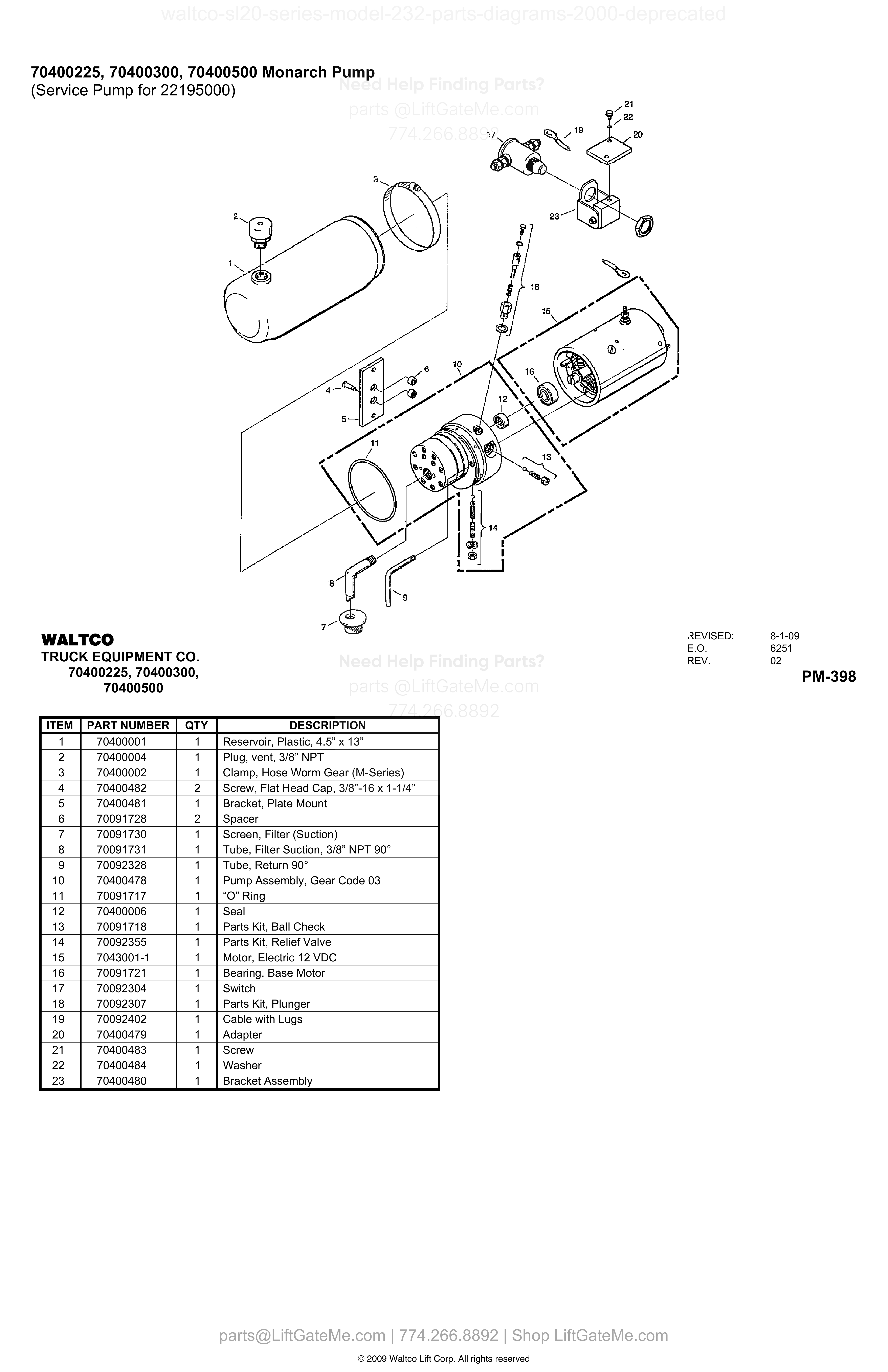
| Item | Qty | Part Number | Description | Actions |
|---|---|---|---|---|
| 1 | 1 | 70400001 | Reservoir, Plastic, 4.5” x 13” | |
| 2 | 1 | 70400004 | Plug, vent, 3/8” NPT | |
| 3 | 1 | 70400002 | Clamp, Hose Worm Gear (M-Series) | |
| 4 | 2 | 70400482 | Screw, Flat Head Cap, 3/8”-16 x 1-1/4” | |
| 5 | 1 | 70400481 | Bracket, Plate Mount | |
| 6 | 2 | 70091728 | Spacer | |
| 7 | 1 | 70091730 | Screen, Filter (Suction) | |
| 8 | 1 | 70091731 | Tube, Filter Suction, 3/8” NPT 90° | |
| 9 | 1 | 70092328 | Tube, Return 90° | |
| 10 | 1 | 70400478 | Pump Assembly, Gear Code 03 | |
| 11 | 1 | 70091717 | “O” Ring | |
| 12 | 1 | 70400006 | Seal | |
| 13 | 1 | 70091718 | Parts Kit, Ball Check | |
| 14 | 1 | 70092355 | Parts Kit, Relief Valve | |
| 15 | 1 | 7043001-1 | Motor, Electric 12 VDC | |
| 16 | 1 | 70091721 | Bearing, Base Motor | |
| 17 | 1 | 70092304 | Switch | |
| 18 | 1 | 70092307 | Parts Kit, Plunger | |
| 19 | 1 | 70092402 | Cable with Lugs | |
| 20 | 1 | 70400479 | Adapter | |
| 21 | 1 | 70400483 | Screw | |
| 22 | 1 | 70400484 | Washer | |
| 23 | 1 | 70400480 | Bracket Assembly |
Reference Notice
Manual links are provided for reference only. If you have any doubt, contact us — we’re happy to verify parts and help you purchase with confidence.
Have your liftgate serial number ready for faster assistance. Where to find it
EXTERNALLY OPERATED PUMP UNIT
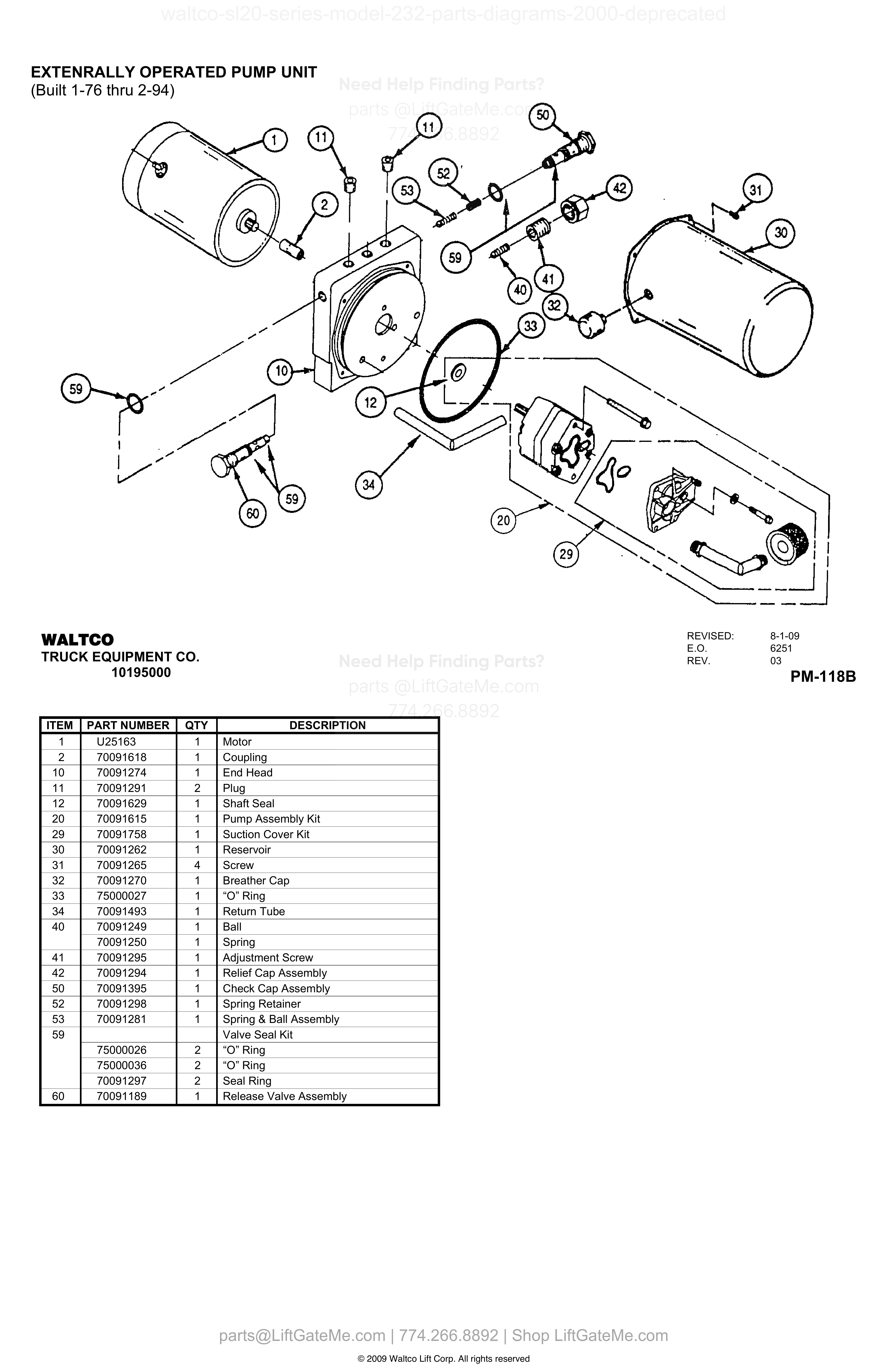
| Item | Qty | Part Number | Description | Actions |
|---|---|---|---|---|
| 1 | 1 | U25163 | Motor | |
| 2 | 1 | 70091618 | Coupling | |
| 10 | 1 | 70091274 | End Head | |
| 11 | 2 | 70091291 | Plug | |
| 12 | 1 | 70091629 | Shaft Seal | |
| 20 | 1 | 70091615 | Pump Assembly Kit | |
| 29 | 1 | 70091758 | Suction Cover Kit | |
| 30 | 1 | 70091262 | Reservoir | |
| 31 | 4 | 70091265 | Screw | |
| 32 | 1 | 70091270 | Breather Cap | |
| 33 | 1 | 75000027 | “O” Ring | |
| 34 | 1 | 70091493 | Return Tube | |
| 40 | 1 | 70091249 | Ball | |
| 40 | 1 | 70091250 | Spring | |
| 41 | 1 | 70091295 | Adjustment Screw | |
| 42 | 1 | 70091294 | Relief Cap Assembly | |
| 50 | 1 | 70091395 | Check Cap Assembly | |
| 52 | 1 | 70091298 | Spring Retainer | |
| 53 | 1 | 70091281 | Spring & Ball Assembly | |
| 59 | Valve Seal Kit | |||
| 59 | 2 | 75000026 | “O” Ring | |
| 59 | 2 | 75000036 | “O” Ring | |
| 59 | 2 | 70091297 | Seal Ring | |
| 60 | 1 | 70091189 | Release Valve Assembly |
70400250, 70400275 MONARCH PUMP
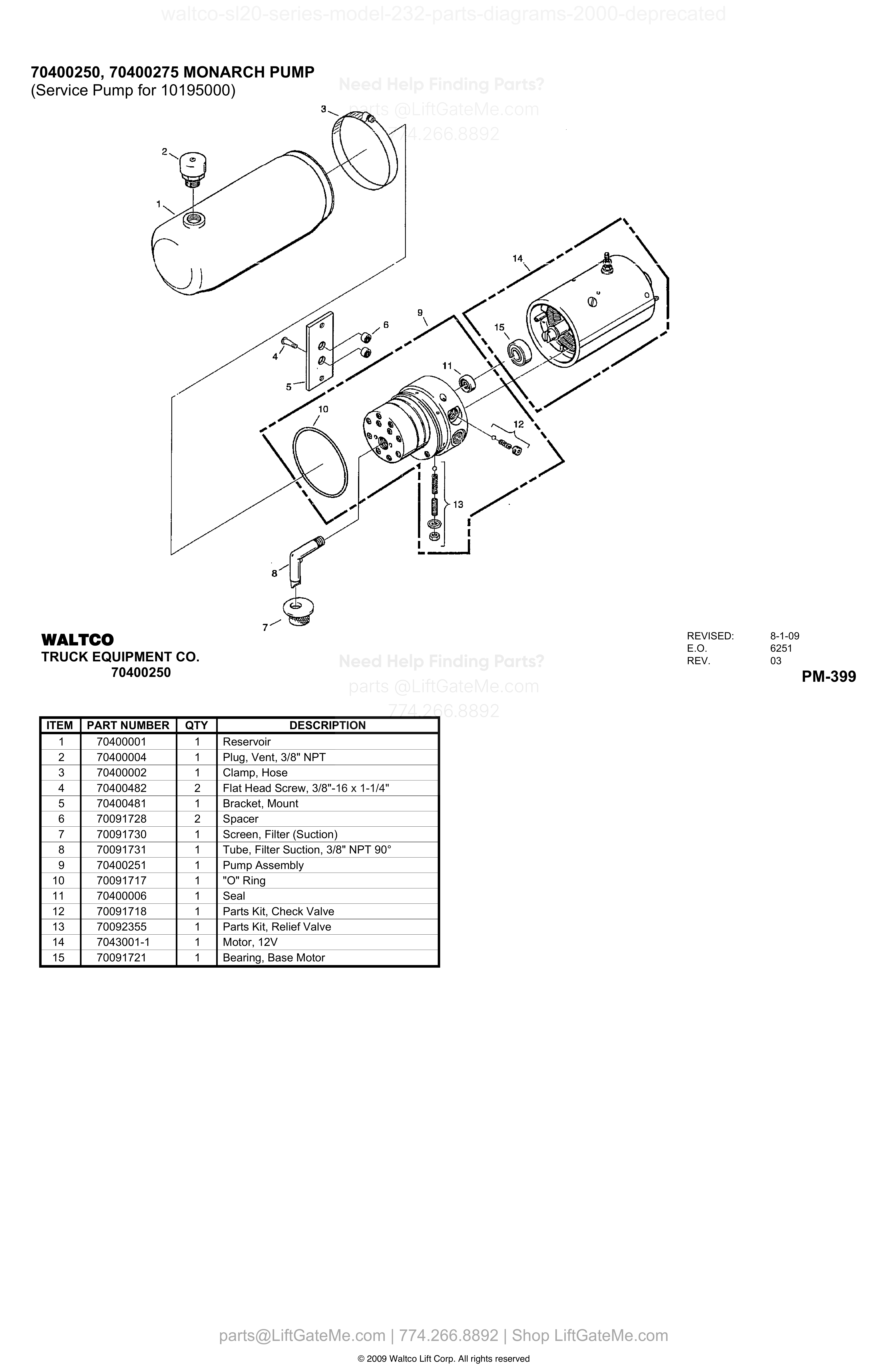
| Item | Qty | Part Number | Description | Actions |
|---|---|---|---|---|
| 1 | 1 | 70400001 | Reservoir | |
| 2 | 1 | 70400004 | Plug, Vent, 3/8” NPT | |
| 3 | 1 | 70400002 | Clamp, Hose | |
| 4 | 2 | 70400482 | Flat Head Screw, 3/8”-16 x 1-1/4” | |
| 5 | 1 | 70400481 | Bracket, Mount | |
| 6 | 2 | 70091728 | Spacer | |
| 7 | 1 | 70091730 | Screen, Filter (Suction) | |
| 8 | 1 | 70091731 | Tube, Filter Suction, 3/8” NPT 90° | |
| 9 | 1 | 70400251 | Pump Assembly | |
| 10 | 1 | 70091717 | "O" Ring | |
| 11 | 1 | 70400006 | Seal | |
| 12 | 1 | 70091718 | Parts Kit, Check Valve | |
| 13 | 1 | 70092355 | Parts Kit, Relief Valve | |
| 14 | 1 | 7043001-1 | Motor, 12V | |
| 15 | 1 | 70091721 | Bearing, Base Motor |
Reference Notice
Manual links are provided for reference only. If you have any doubt, contact us — we’re happy to verify parts and help you purchase with confidence.
Have your liftgate serial number ready for faster assistance. Where to find it
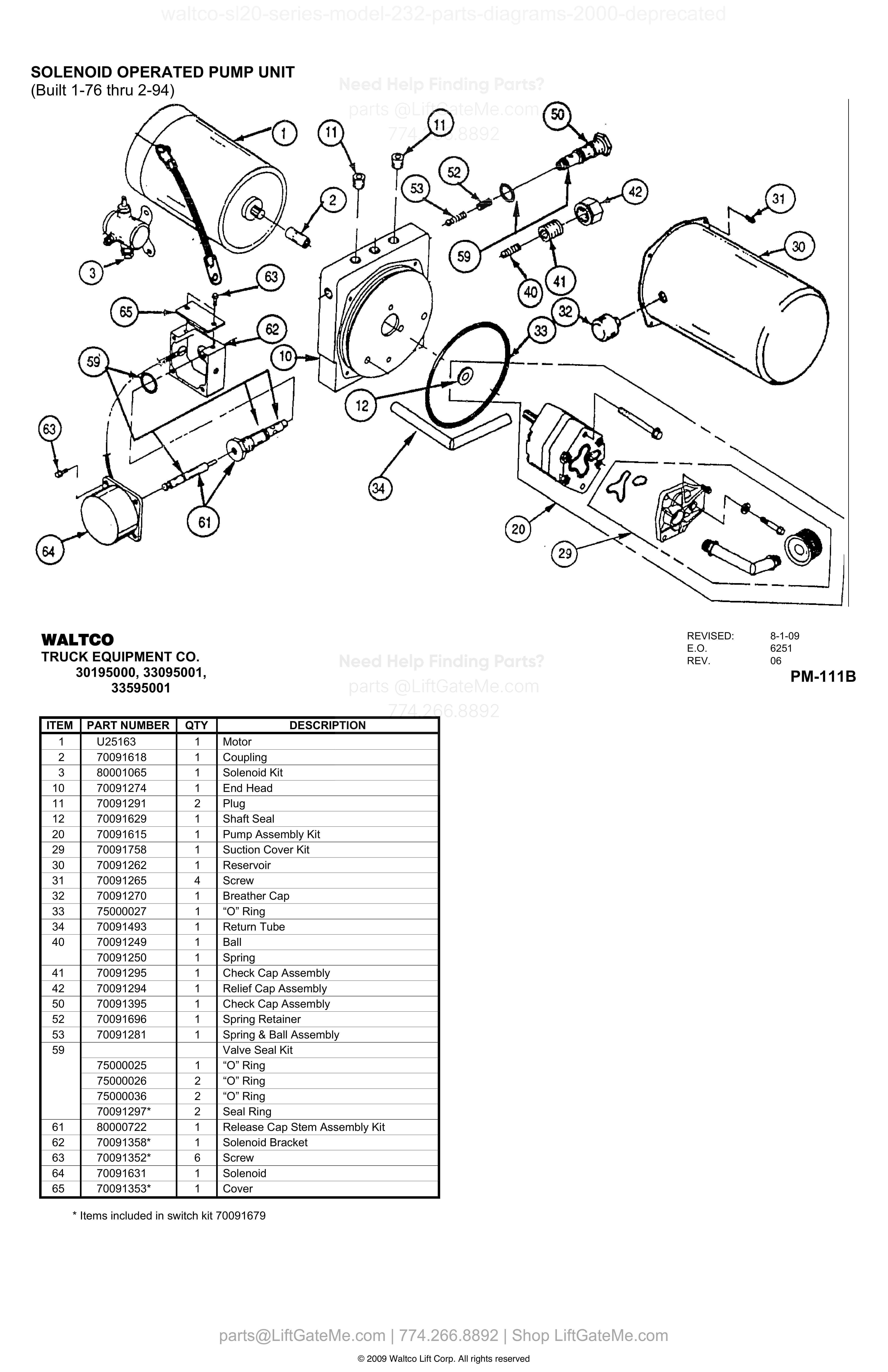
SOLENOID OPERATED PUMP UNIT
| Item | Qty | Part Number | Description | Actions |
|---|---|---|---|---|
| 1 | 1 | U25163 | Motor | |
| 2 | 1 | 70091618 | Coupling | |
| 3 | 1 | 80001065 | Solenoid Kit | |
| 10 | 1 | 70091274 | End Head | |
| 11 | 2 | 70091291 | Plug | |
| 12 | 1 | 70091629 | Shaft Seal | |
| 20 | 1 | 70091615 | Pump Assembly Kit | |
| 29 | 1 | 70091758 | Suction Cover Kit | |
| 30 | 1 | 70091262 | Reservoir | |
| 31 | 4 | 70091265 | Screw | |
| 32 | 1 | 70091270 | Breather Cap | |
| 33 | 1 | 75000027 | “O” Ring | |
| 34 | 1 | 70091493 | Return Tube | |
| 40 | 1 | 70091249 | Ball | |
| 40 | 1 | 70091250 | Spring | |
| 41 | 1 | 70091295 | Check Cap Assembly | |
| 42 | 1 | 70091294 | Relief Cap Assembly | |
| 50 | 1 | 70091395 | Check Cap Assembly | |
| 52 | 1 | 70091696 | Spring Retainer | |
| 53 | 1 | 70091281 | Spring & Ball Assembly | |
| 59 | Valve Seal Kit | |||
| 59 | 1 | 75000025 | “O” Ring | |
| 59 | 2 | 75000026 | “O” Ring | |
| 59 | 2 | 75000036 | “O” Ring | |
| 59 | 2 | 70091297* | Seal Ring | |
| 61 | 1 | 80000722 | Release Cap Stem Assembly Kit | |
| 62 | 1 | 70091358* | Solenoid Bracket | |
| 63 | 6 | 70091352* | Screw | |
| 64 | 1 | 70091631 | Solenoid | |
| 65 | 1 | 70091353* | Cover |
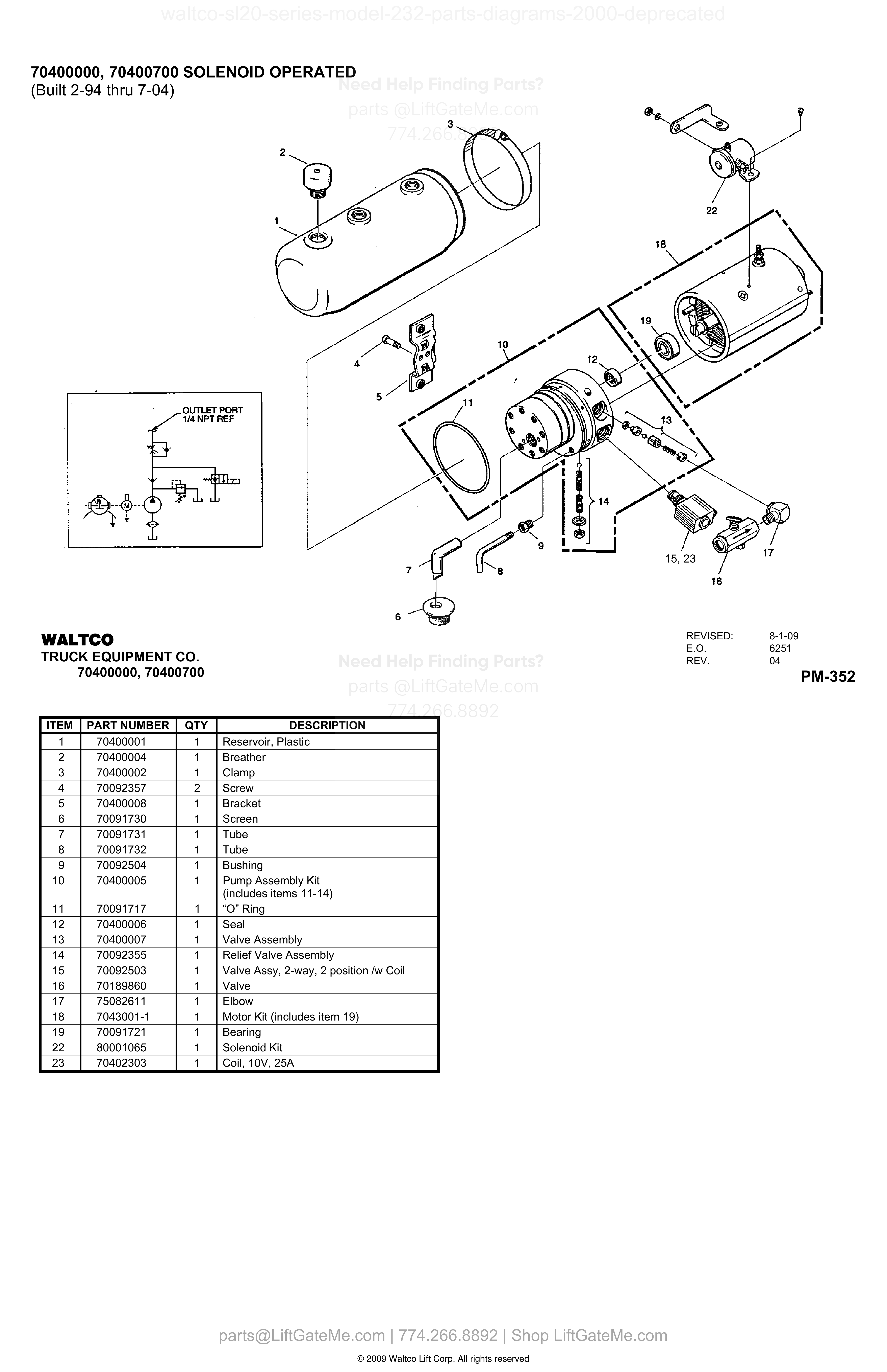
70400000, 70400700 SOLENOID OPERATED
| Item | Qty | Part Number | Description | Actions |
|---|---|---|---|---|
| 1 | 1 | 70400001 | Reservoir, Plastic | |
| 2 | 1 | 70400004 | Breather | |
| 3 | 1 | 70400002 | Clamp | |
| 4 | 2 | 70092357 | Screw | |
| 5 | 1 | 70400008 | Bracket | |
| 6 | 1 | 70091730 | Screen | |
| 7 | 1 | 70091731 | Tube | |
| 8 | 1 | 70091732 | Tube | |
| 9 | 1 | 70092504 | Bushing | |
| 10 | 1 | 70400005 | Pump Assembly Kit (includes items 11-14) | |
| 11 | 1 | 70091717 | “O” Ring | |
| 12 | 1 | 70400006 | Seal | |
| 13 | 1 | 70400007 | Valve Assembly | |
| 14 | 1 | 70092355 | Relief Valve Assembly | |
| 15 | 1 | 70092503 | Valve Assy, 2-way, 2 position /w Coil | |
| 16 | 1 | 70189860 | Valve | |
| 17 | 1 | 75082611 | Elbow | |
| 18 | 1 | 7043001-1 | Motor Kit (includes item 19) | |
| 19 | 1 | 70091721 | Bearing | |
| 22 | 1 | 80001065 | Solenoid Kit | |
| 23 | 1 | 70402303 | Coil, 10V, 25A |
Reference Notice
Manual links are provided for reference only. If you have any doubt, contact us — we’re happy to verify parts and help you purchase with confidence.
Have your liftgate serial number ready for faster assistance. Where to find it
70401400, 70401450, 70401700, 70401750, 70401900, 70401950, 70430320 GRAVITY DOWN ELECTROPAK

| Item | Qty | Part Number | Description | Actions |
|---|---|---|---|---|
| 1 | 1 | 70401456 B | Reservoir (Metal) | |
| 1 | 1 | 70400001 C | Reservoir (Plastic) | |
| 2 | 1 | 70400055 B | Breather Plug | |
| 3 | 6 | 70091738 B | Screw, 10-24 x 3/8” lg. (For Metal Reservoir) | |
| 3 | 1 | 70400002 C | Clamp (For Plastic Reservoir) | |
| 4 | 4 | 75086000 A | Screw, socket flat head cap, 1/4-20 | |
| 5 | 1 | 70401407 A | Plate | |
| 6 | 1 | 70401408 | Grommet | |
| 7 | 1 | 70401435 | Fitting, male 7/16” SAE 37° Flare | |
| 8 | 1 | 70401409 | Grommet | |
| 9 | 1 | 70401430 | Fitting, barbed | |
| 10 | 1 | 70091734 | Breather | |
| 11 | 1 | 70401410 | Pump Assembly | |
| 12 | 1 | 70091717 | O-ring | |
| 13 | 1 | 70401411 D | Flow Control Valve, NPT Threads | |
| 13 | 1 | 70401711 E | Flow Control Valve, SAE Threads w/ “O” Ring | |
| 14 | 1 | 70400006 | Seal | |
| 15 | 1 | 70401412 | Sight Glass | |
| 16 | 1 | 70401413 | Relief Valve | |
| 17 | 1 | 70401415 | Drain Plug | |
| 18 | 1 | 70401414 | Plug, Check valve | |
| 19 | 1 | 70401406 | Return Tube | |
| 20 | 1 | 70401405 | Return Tube | |
| 21 | 1 | 70091730 | Filter | |
| 22 | 1 | 70091731 | Suction Tube | |
| 23 | 1 | 70092503 | Valve Assy, 2-way/2pos with Coil | |
| 24 | 1 | 70091721 | Bearing | |
| 25 | 1 | 75089833 | Starter Solenoid | |
| 26 | 1 | 7043001-1 | Motor | |
| 27 | 1 | 70401416 | Check Valve | |
| 28 | 1 | 70402303 | Coil, 10V, 25A |
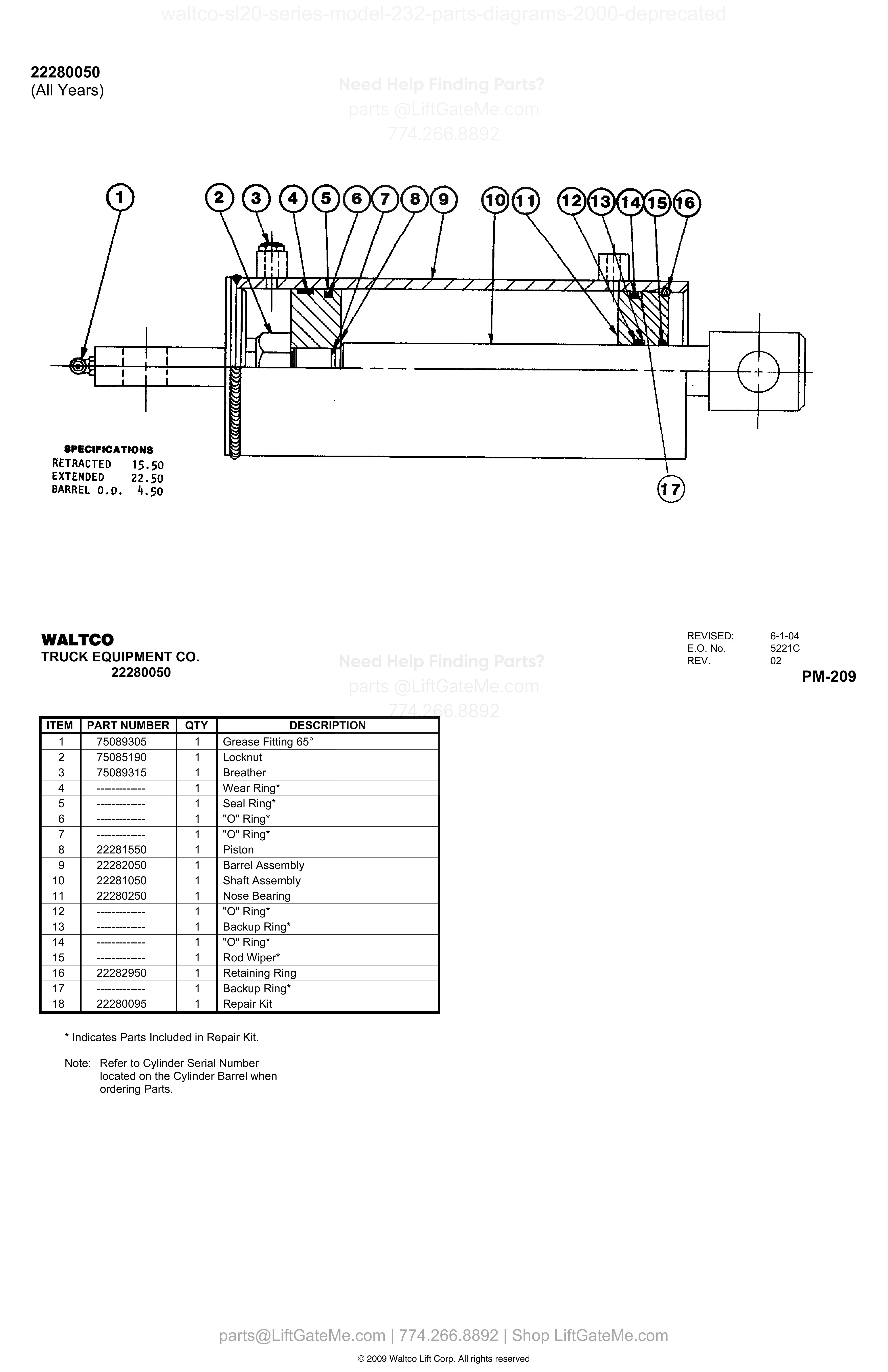
22280050
| Item | Qty | Part Number | Description | Actions |
|---|---|---|---|---|
| 1 | 1 | 75089305 | Grease Fitting 65° | |
| 2 | 1 | 75085190 | Locknut | |
| 3 | 1 | 75089315 | Breather | |
| 4 | 1 | ------------- | Wear Ring* | |
| 5 | 1 | ------------- | Seal Ring* | |
| 6 | 1 | ------------- | "O" Ring* | |
| 7 | 1 | ------------- | "O" Ring* | |
| 8 | 1 | 22281550 | Piston | |
| 9 | 1 | 22282050 | Barrel Assembly | |
| 10 | 1 | 22281050 | Shaft Assembly | |
| 11 | 1 | 22280250 | Nose Bearing | |
| 12 | 1 | ------------- | "O" Ring* | |
| 13 | 1 | ------------- | Backup Ring* | |
| 14 | 1 | ------------- | "O" Ring* | |
| 15 | 1 | ------------- | Rod Wiper* | |
| 16 | 1 | 22282950 | Retaining Ring | |
| 17 | 1 | ------------- | Backup Ring* | |
| 18 | 1 | 22280095 | Repair Kit |
Reference Notice
Manual links are provided for reference only. If you have any doubt, contact us — we’re happy to verify parts and help you purchase with confidence.
Have your liftgate serial number ready for faster assistance. Where to find it
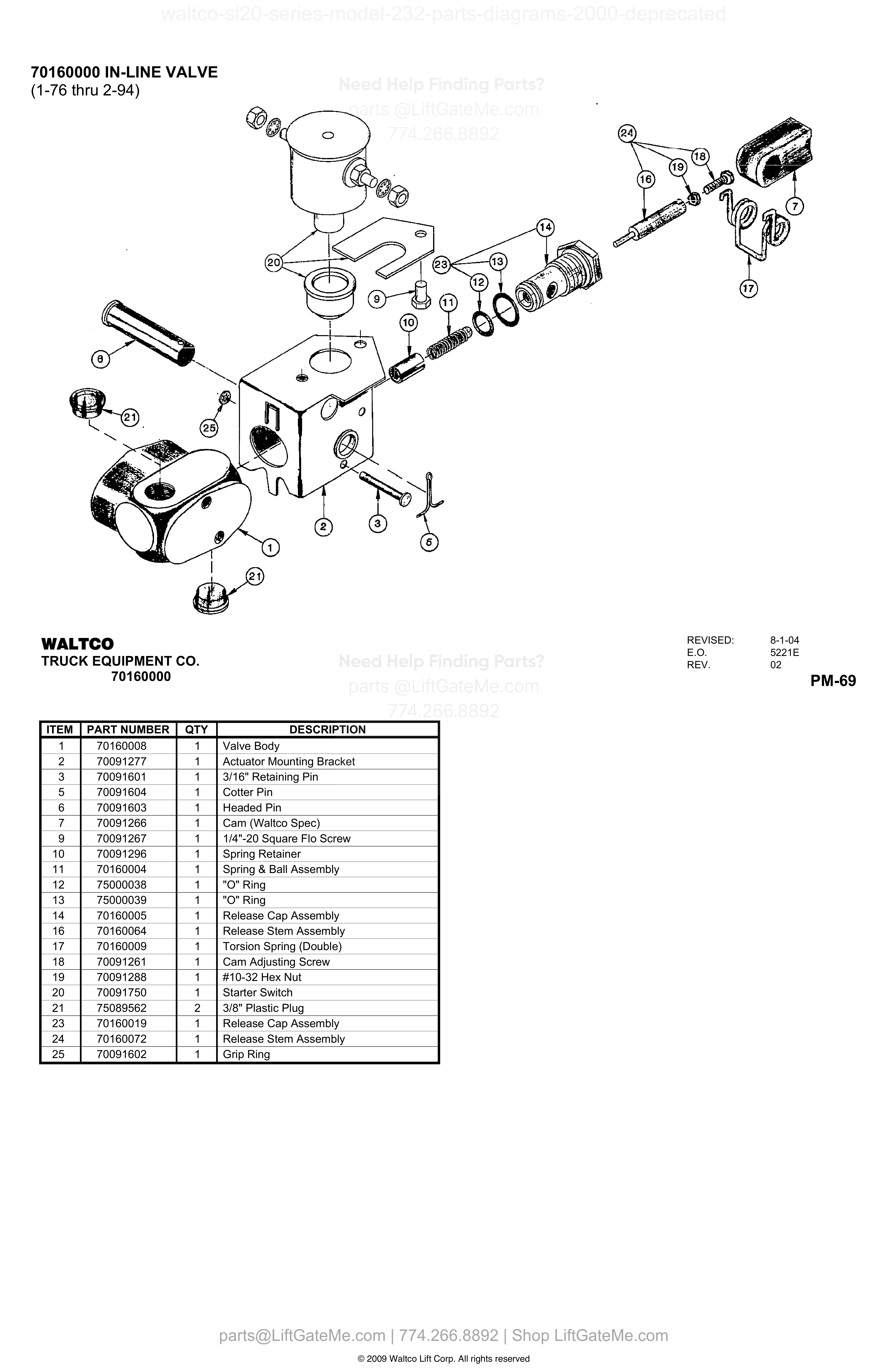
70160000 IN-LINE VALVE
| Item | Qty | Part Number | Description | Actions |
|---|---|---|---|---|
| 1 | 1 | 70160008 | Valve Body | |
| 2 | 1 | 70091277 | Actuator Mounting Bracket | |
| 3 | 1 | 70091601 | 3/16" Retaining Pin | |
| 5 | 1 | 70091604 | Cotter Pin | |
| 6 | 1 | 70091603 | Headed Pin | |
| 7 | 1 | 70091266 | Cam (Waltco Spec) | |
| 9 | 1 | 70091267 | 1/4"-20 Square Flo Screw | |
| 10 | 1 | 70091296 | Spring Retainer | |
| 11 | 1 | 70160004 | Spring & Ball Assembly | |
| 12 | 1 | 75000038 | "O" Ring | |
| 13 | 1 | 75000039 | "O" Ring | |
| 14 | 1 | 70160005 | Release Cap Assembly | |
| 16 | 1 | 70160064 | Release Stem Assembly | |
| 17 | 1 | 70160009 | Torsion Spring (Double) | |
| 18 | 1 | 70091261 | Cam Adjusting Screw | |
| 19 | 1 | 70091288 | #10-32 Hex Nut | |
| 20 | 1 | 70091750 | Starter Switch | |
| 21 | 2 | 75089562 | 3/8" Plastic Plug | |
| 23 | 1 | 70160019 | Release Cap Assembly | |
| 24 | 1 | 70160072 | Release Stem Assembly | |
| 25 | 1 | 70091602 | Grip Ring |
Need help confirming the correct part?
Share model, serial, and item number.
Fast technical support
Use this after reviewing the diagram and table. We can verify compatibility before purchase.
Phone
(774) 266-8892Send your details and we will help identify the right replacement part.
Contact SupportImportant Diagram Notice
These diagrams are for reference only.
- Due to unintended occasional data alignment issues, a page table may differ slightly from the original OEM PDF.
- Please verify details against the original PDF file.
- Contact our team anytime for part number confirmation.
Reference mismatch detected