
Waltco P-Series Model 140 Liftgate Parts Diagrams | Approximate Years Pre-2000
Pre-2000 Waltco P-Series Model 140 liftgate parts reference
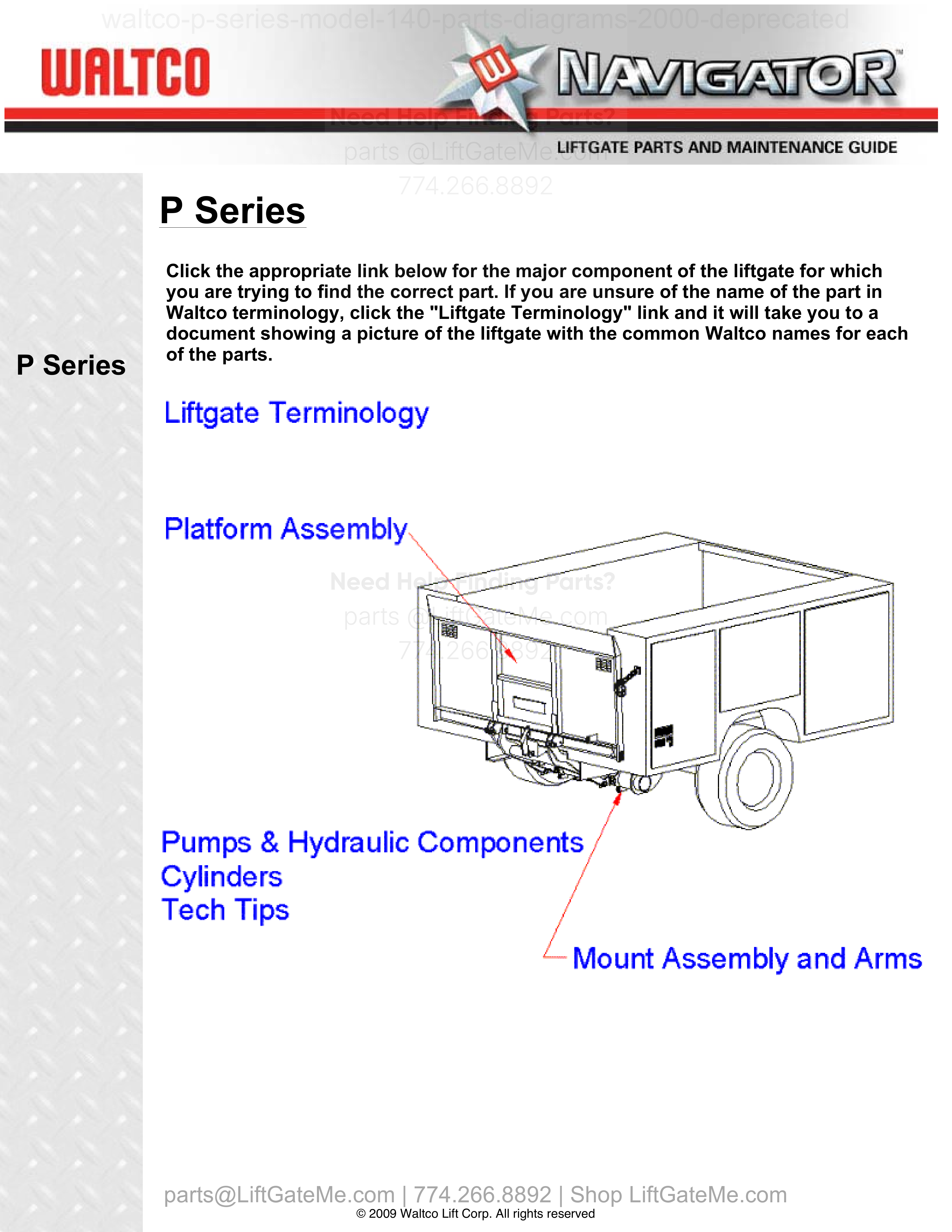
Find pre-2000 Waltco P-Series Model 140 parts diagrams for legacy light-duty liftgates. These breakdowns help match part numbers and confirm replacement liftgate parts before ordering.
Compatibility and Purchasing Notice
Although the information on this page is taken from an OEM lift gate manual, if you're unsure whether this data matches your exact model and year, PLEASE contact our team. Part numbers can vary by year - even within the same model - and we're always happy to confirm the correct parts for you.
Have your liftgate serial number ready for faster assistance. Where to find it
i


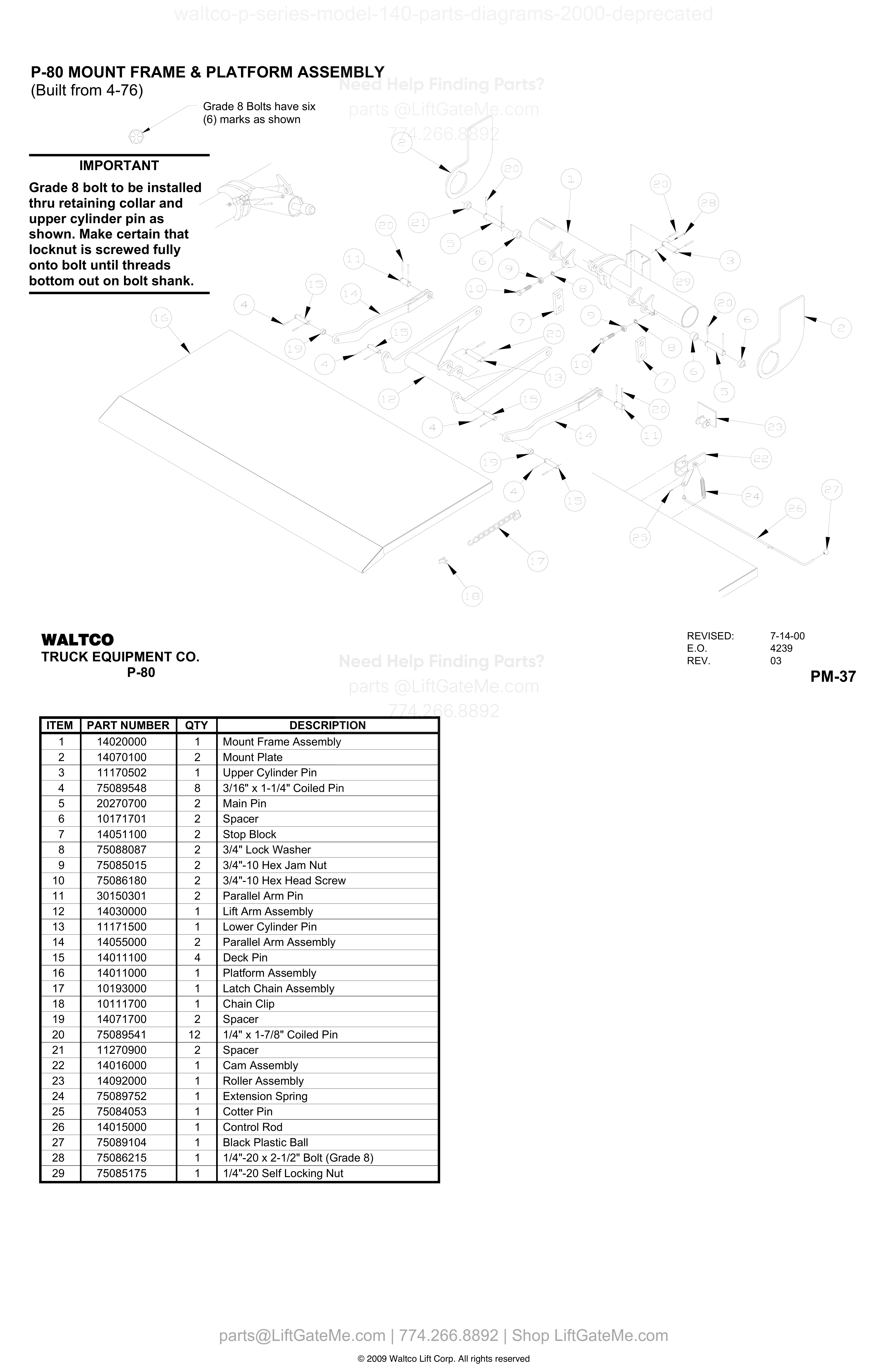
P-80 MOUNT FRAME & PLATFORM ASSEMBLY (Built from 4-76)
| Item | Qty | Part Number | Description | Actions |
|---|---|---|---|---|
| 1 | 1 | 14020000 | Mount Frame Assembly | |
| 2 | 2 | 14070100 | Mount Plate | |
| 3 | 1 | 11170502 | Upper Cylinder Pin | |
| 4 | 8 | 75089548 | 3/16" x 1-1/4" Coiled Pin | |
| 5 | 2 | 20270700 | Main Pin | |
| 6 | 2 | 10171701 | Spacer | |
| 7 | 2 | 14051100 | Stop Block | |
| 8 | 2 | 75088087 | 3/4" Lock Washer | |
| 9 | 2 | 75085015 | 3/4"-10 Hex Jam Nut | |
| 10 | 2 | 75086180 | 3/4"-10 Hex Head Screw | |
| 11 | 2 | 30150301 | Parallel Arm Pin | |
| 12 | 1 | 14030000 | Lift Arm Assembly | |
| 13 | 1 | 11171500 | Lower Cylinder Pin | |
| 14 | 2 | 14055000 | Parallel Arm Assembly | |
| 15 | 4 | 14011100 | Deck Pin | |
| 16 | 1 | 14011000 | Platform Assembly | |
| 17 | 1 | 10193000 | Latch Chain Assembly | |
| 18 | 1 | 10111700 | Chain Clip | |
| 19 | 2 | 14071700 | Spacer | |
| 20 | 12 | 75089541 | 1/4" x 1-7/8" Coiled Pin | |
| 21 | 2 | 11270900 | Spacer | |
| 22 | 1 | 14016000 | Cam Assembly | |
| 23 | 1 | 14092000 | Roller Assembly | |
| 24 | 1 | 75089752 | Extension Spring | |
| 25 | 1 | 75084053 | Cotter Pin | |
| 26 | 1 | 14015000 | Control Rod | |
| 27 | 1 | 75089104 | Black Plastic Ball | |
| 28 | 1 | 75086215 | 1/4"-20 x 2-1/2" Bolt (Grade 8) | |
| 29 | 1 | 75085175 | 1/4"-20 Self Locking Nut |
Reference Notice
Manual links are provided for reference only. If you have any doubt, contact us — we’re happy to verify parts and help you purchase with confidence.
Have your liftgate serial number ready for faster assistance. Where to find it
i

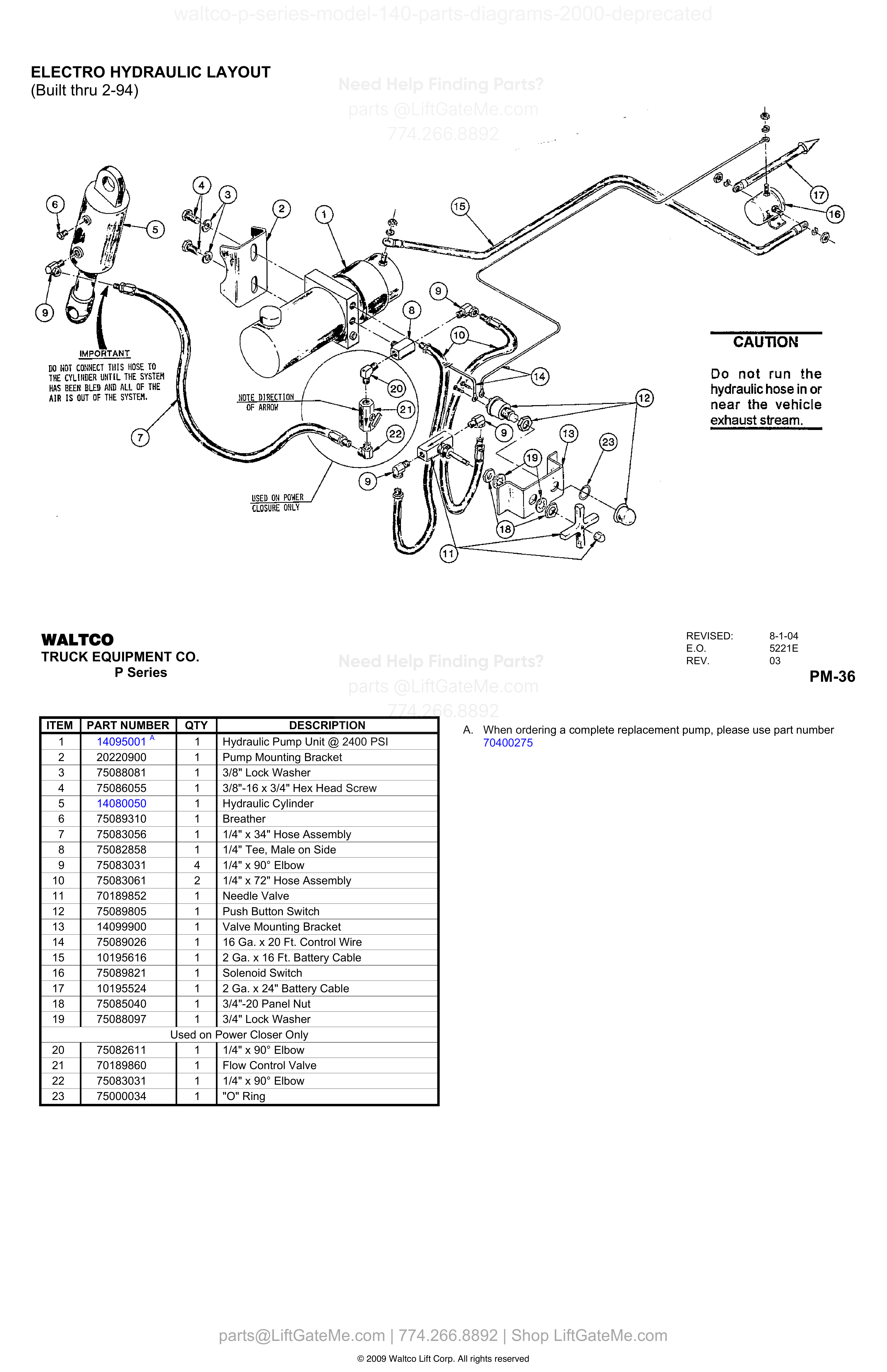
ELECTRO HYDRAULIC LAYOUT (Built thru 2-94)
| Item | Qty | Part Number | Description | Actions |
|---|---|---|---|---|
| 1 | 1 | 14095001 A | Hydraulic Pump Unit @ 2400 PSI | |
| 2 | 1 | 20220900 | Pump Mounting Bracket | |
| 3 | 1 | 75088081 | 3/8" Lock Washer | |
| 4 | 1 | 75086055 | 3/8"-16 x 3/4" Hex Head Screw | |
| 5 | 1 | 14080050 | Hydraulic Cylinder | |
| 6 | 1 | 75089310 | Breather | |
| 7 | 1 | 75083056 | 1/4" x 34" Hose Assembly | |
| 8 | 1 | 75082858 | 1/4" Tee, Male on Side | |
| 9 | 4 | 75083031 | 1/4" x 90° Elbow | |
| 10 | 2 | 75083061 | 1/4" x 72" Hose Assembly | |
| 11 | 1 | 70189852 | Needle Valve | |
| 12 | 1 | 75089805 | Push Button Switch | |
| 13 | 1 | 14099900 | Valve Mounting Bracket | |
| 14 | 1 | 75089026 | 16 Ga. x 20 Ft. Control Wire | |
| 15 | 1 | 10195616 | 2 Ga. x 16 Ft. Battery Cable | |
| 16 | 1 | 75089821 | Solenoid Switch | |
| 17 | 1 | 10195524 | 2 Ga. x 24" Battery Cable | |
| 18 | 1 | 75085040 | 3/4"-20 Panel Nut | |
| 19 | 1 | 75088097 | 3/4" Lock Washer | |
| 20 | 1 | 75082611 | 1/4" x 90° Elbow | |
| 21 | 1 | 70189860 | Flow Control Valve | |
| 22 | 1 | 75083031 | 1/4" x 90° Elbow | |
| 23 | 1 | 75000034 | "O" Ring |
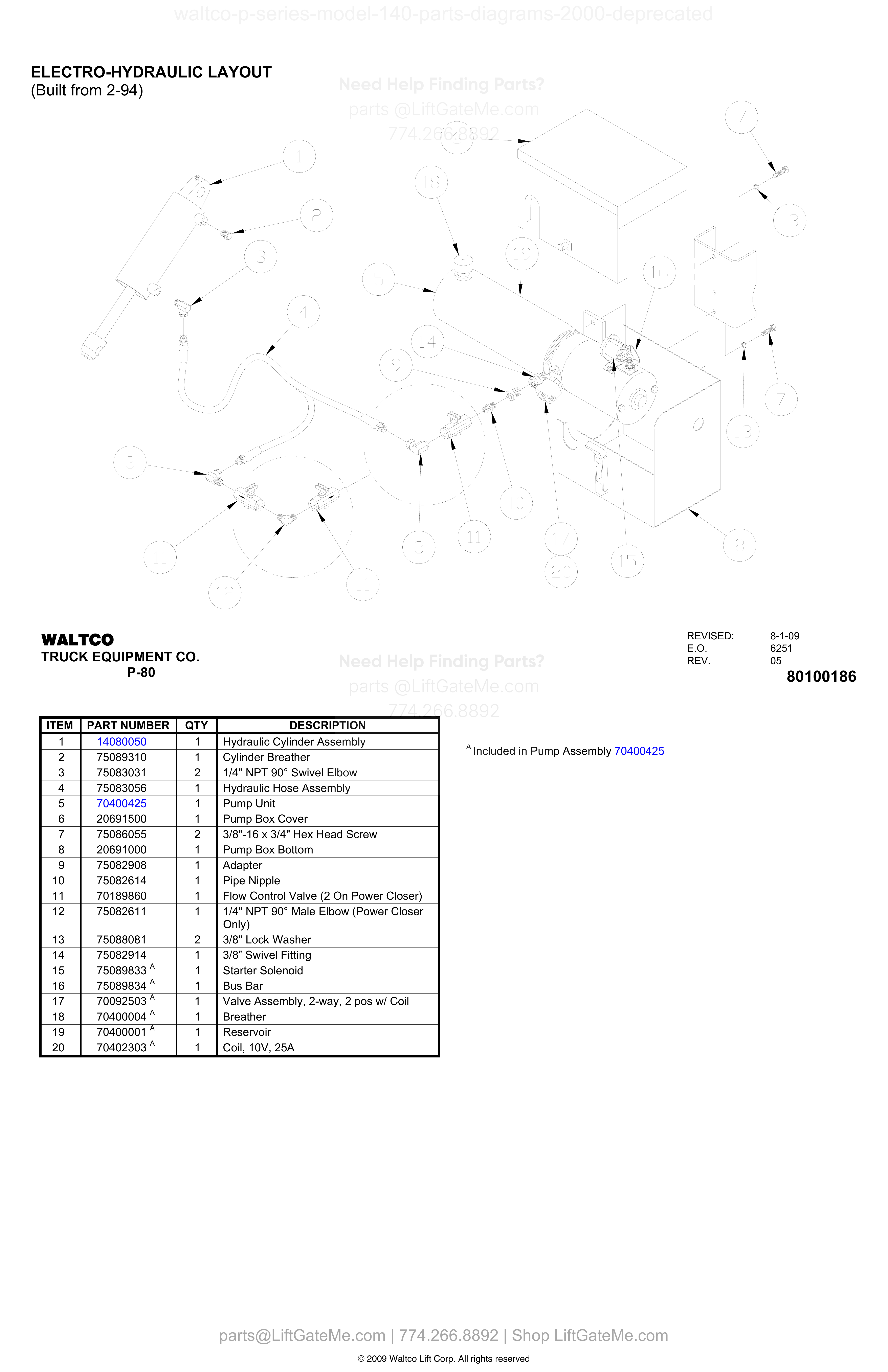
ELECTRO-HYDRAULIC LAYOUT (Built from 2-94)
| Item | Qty | Part Number | Description | Actions |
|---|---|---|---|---|
| 1 | 1 | 14080050 | Hydraulic Cylinder Assembly | |
| 2 | 1 | 75089310 | Cylinder Breather | |
| 3 | 2 | 75083031 | 1/4" NPT 90° Swivel Elbow | |
| 4 | 1 | 75083056 | Hydraulic Hose Assembly | |
| 5 | 1 | 70400425 | Pump Unit | |
| 6 | 1 | 20691500 | Pump Box Cover | |
| 7 | 2 | 75086055 | 3/8"-16 x 3/4" Hex Head Screw | |
| 8 | 1 | 20691000 | Pump Box Bottom | |
| 9 | 1 | 75082908 | Adapter | |
| 10 | 1 | 75082614 | Pipe Nipple | |
| 11 | 1 | 70189860 | Flow Control Valve (2 On Power Closer) | |
| 12 | 1 | 75082611 | 1/4" NPT 90° Male Elbow (Power Closer Only) | |
| 13 | 2 | 75088081 | 3/8" Lock Washer | |
| 14 | 1 | 75082914 | 3/8" Swivel Fitting | |
| 15 | 1 | 75089833 A | Starter Solenoid | |
| 16 | 1 | 75089834 A | Bus Bar | |
| 17 | 1 | 70092503 A | Valve Assembly, 2-way, 2 pos w/ Coil | |
| 18 | 1 | 70400004 A | Breather | |
| 19 | 1 | 70400001 A | Reservoir | |
| 20 | 1 | 70402303 A | Coil, 10V, 25A |
Reference Notice
Manual links are provided for reference only. If you have any doubt, contact us — we’re happy to verify parts and help you purchase with confidence.
Have your liftgate serial number ready for faster assistance. Where to find it
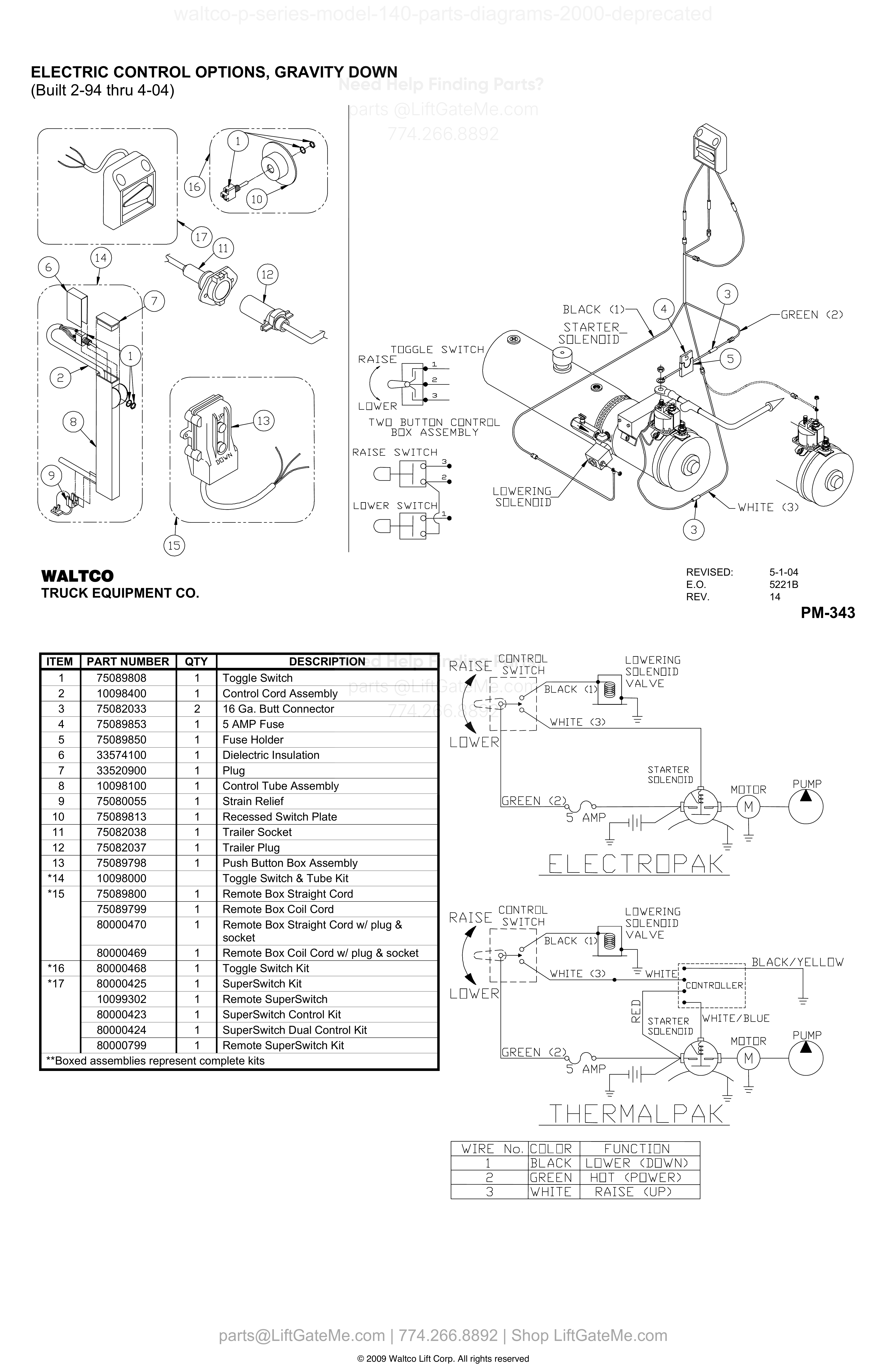
ELECTRIC CONTROL OPTIONS, GRAVITY DOWN
| Item | Qty | Part Number | Description | Actions |
|---|---|---|---|---|
| 1 | 1 | 75089808 | Toggle Switch | |
| 2 | 1 | 10098400 | Control Cord Assembly | |
| 3 | 2 | 75082033 | 16 Ga. Butt Connector | |
| 4 | 1 | 75089853 | 5 AMP Fuse | |
| 5 | 1 | 75089850 | Fuse Holder | |
| 6 | 1 | 33574100 | Dielectric Insulation | |
| 7 | 1 | 33520900 | Plug | |
| 8 | 1 | 10098100 | Control Tube Assembly | |
| 9 | 1 | 75080055 | Strain Relief | |
| 10 | 1 | 75089813 | Recessed Switch Plate | |
| 11 | 1 | 75082038 | Trailer Socket | |
| 12 | 1 | 75082037 | Trailer Plug | |
| 13 | 1 | 75089798 | Push Button Box Assembly | |
| *14 | 10098000 | Toggle Switch & Tube Kit | ||
| *15 | 1 | 75089800 | Remote Box Straight Cord | |
| *15 | 1 | 75089799 | Remote Box Coil Cord | |
| *15 | 1 | 80000470 | Remote Box Straight Cord w/ plug & socket | |
| *15 | 1 | 80000469 | Remote Box Coil Cord w/ & socket | |
| *16 | 1 | 80000468 | Toggle Switch Kit | |
| *17 | 1 | 80000425 | SuperSwitch Kit | |
| *17 | 1 | 10099302 | Remote SuperSwitch | |
| *17 | 1 | 80000423 | SuperSwitch Control Kit | |
| *17 | 1 | 80000424 | SuperSwitch Dual Control Kit | |
| *17 | 1 | 80000799 | Remote SuperSwitch Kit |
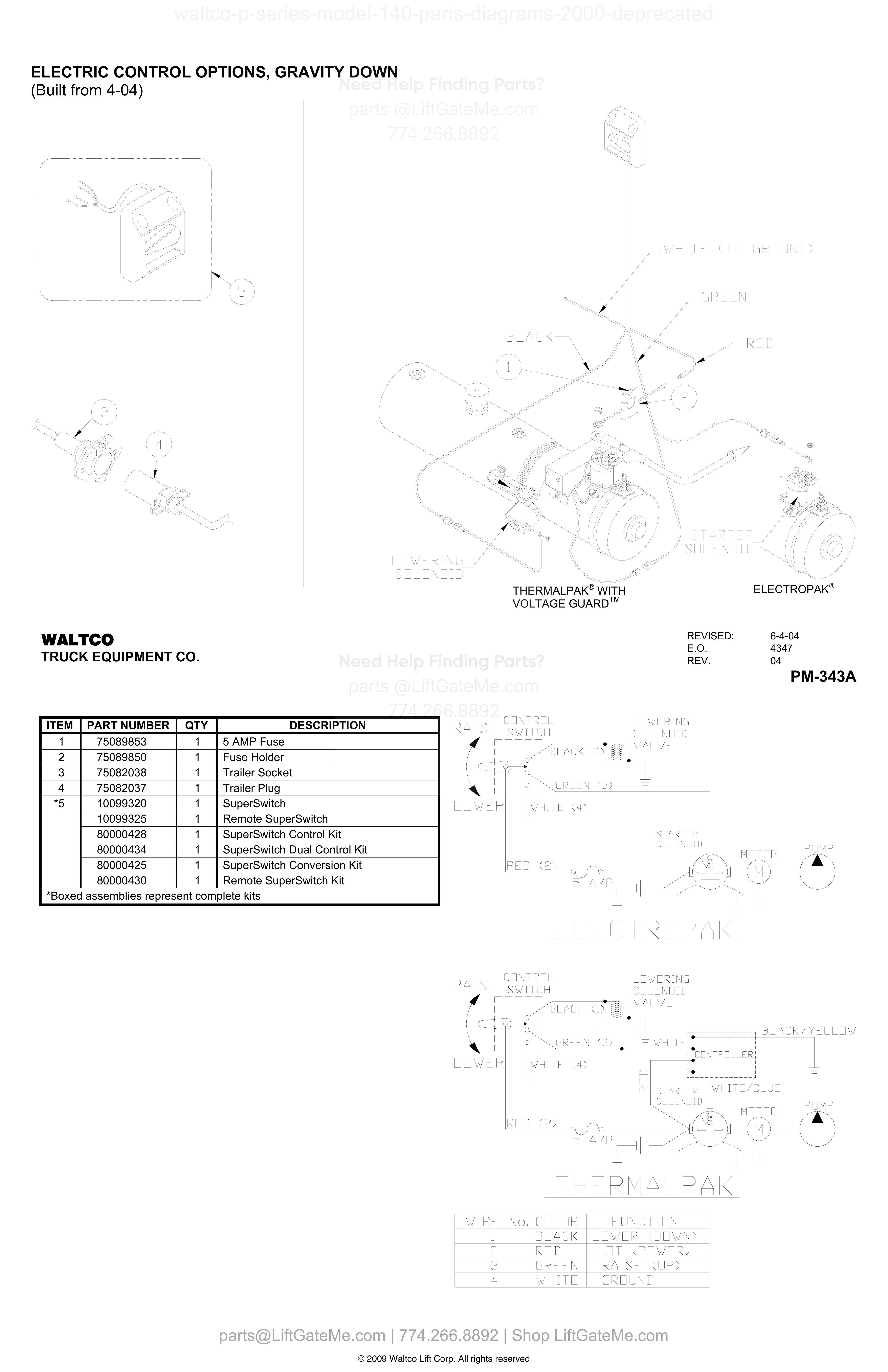
ELECTRIC CONTROL OPTIONS, GRAVITY DOWN (Built from 4-04)
| Item | Qty | Part Number | Description | Actions |
|---|---|---|---|---|
| 1 | 1 | 75089853 | 5 AMP Fuse | |
| 2 | 1 | 75089850 | Fuse Holder | |
| 3 | 1 | 75082038 | Trailer Socket | |
| 4 | 1 | 75082037 | Trailer Plug | |
| *5 | 1 | 10099320 | SuperSwitch | |
| *5 | 1 | 10099325 | Remote SuperSwitch | |
| *5 | 1 | 80000428 | SuperSwitch Control Kit | |
| *5 | 1 | 80000434 | SuperSwitch Dual Control Kit | |
| *5 | 1 | 80000425 | SuperSwitch Conversion Kit | |
| *5 | 1 | 80000430 | Remote SuperSwitch Kit |
Reference Notice
Manual links are provided for reference only. If you have any doubt, contact us — we’re happy to verify parts and help you purchase with confidence.
Have your liftgate serial number ready for faster assistance. Where to find it
i

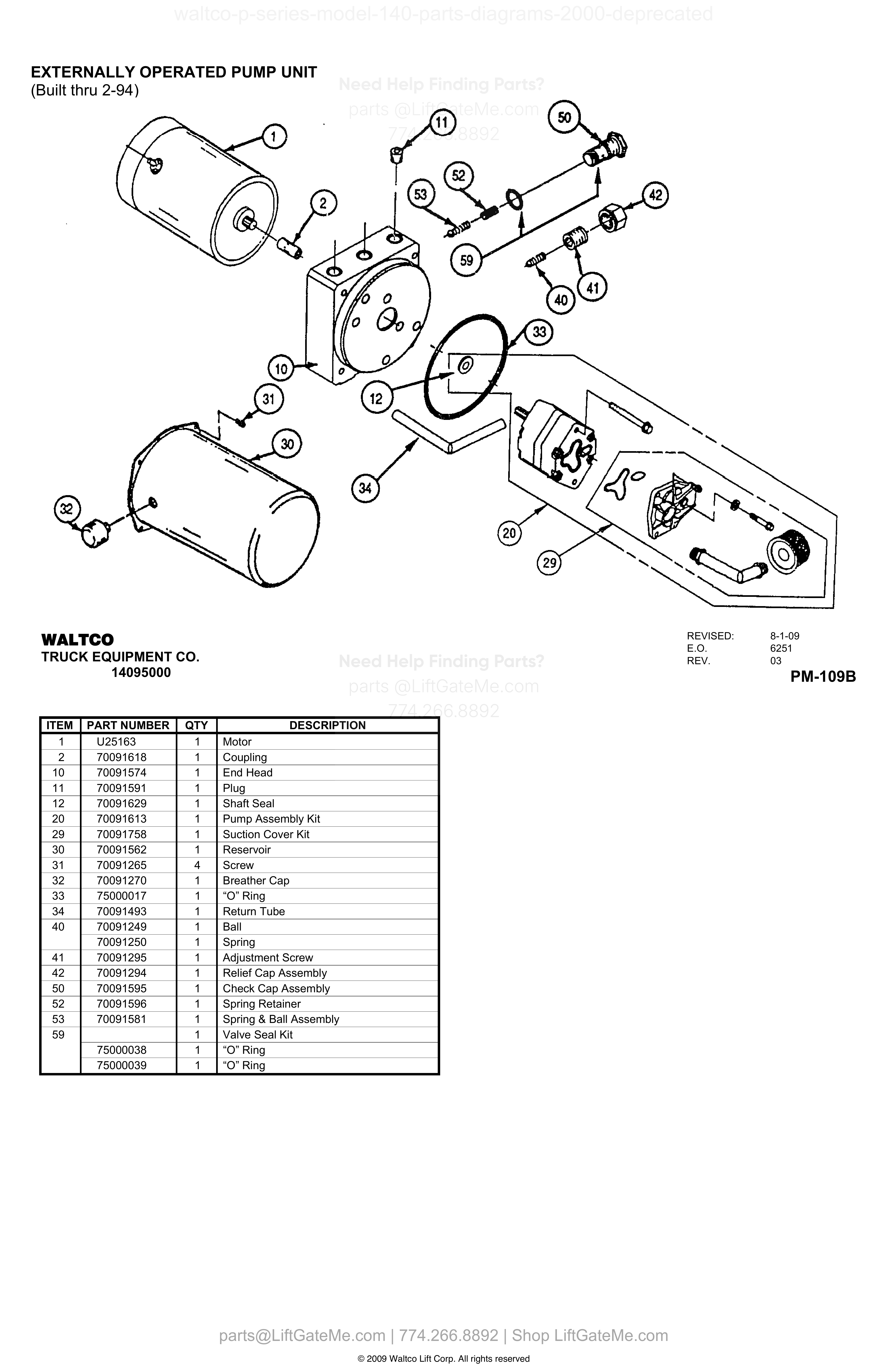
EXTERNALLY OPERATED PUMP UNIT
| Item | Qty | Part Number | Description | Actions |
|---|---|---|---|---|
| 1 | 1 | U25163 | Motor | |
| 2 | 1 | 70091618 | Coupling | |
| 10 | 1 | 70091574 | End Head | |
| 11 | 1 | 70091591 | Plug | |
| 12 | 1 | 70091629 | Shaft Seal | |
| 20 | 1 | 70091613 | Pump Assembly Kit | |
| 29 | 1 | 70091758 | Suction Cover Kit | |
| 30 | 1 | 70091562 | Reservoir | |
| 31 | 4 | 70091265 | Screw | |
| 32 | 1 | 70091270 | Breather Cap | |
| 33 | 1 | 75000017 | “O” Ring | |
| 34 | 1 | 70091493 | Return Tube | |
| 40 | 1 | 70091249 | Ball | |
| 40 | 1 | 70091250 | Spring | |
| 41 | 1 | 70091295 | Adjustment Screw | |
| 42 | 1 | 70091294 | Relief Cap Assembly | |
| 50 | 1 | 70091595 | Check Cap Assembly | |
| 52 | 1 | 70091596 | Spring Retainer | |
| 53 | 1 | 70091581 | Spring & Ball Assembly | |
| 59 | 1 | Valve Seal Kit | ||
| 59 | 1 | 75000038 | “O” Ring | |
| 59 | 1 | 75000039 | “O” Ring |
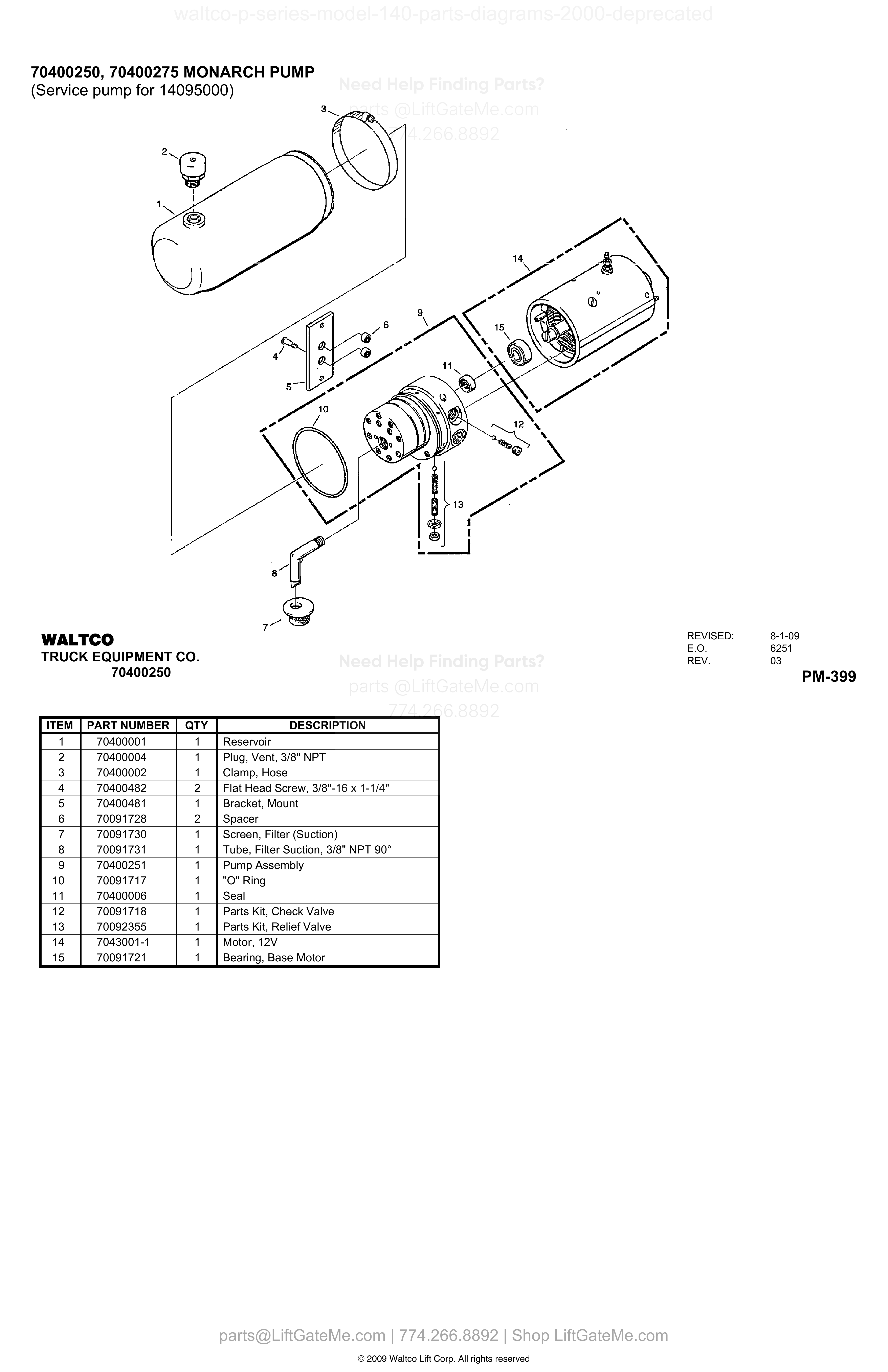
70400250, 70400275 MONARCH PUMP (Service pump for 14095000)
| Item | Qty | Part Number | Description | Actions |
|---|---|---|---|---|
| 1 | 1 | 70400001 | Reservoir | |
| 2 | 1 | 70400004 | Plug, Vent, 3/8” NPT | |
| 3 | 1 | 70400002 | Clamp, Hose | |
| 4 | 2 | 70400482 | Flat Head Screw, 3/8”-16 x 1-1/4” | |
| 5 | 1 | 70400481 | Bracket, Mount | |
| 6 | 2 | 70091728 | Spacer | |
| 7 | 1 | 70091730 | Screen, Filter (Suction) | |
| 8 | 1 | 70091731 | Tube, Filter Suction, 3/8” NPT 90° | |
| 9 | 1 | 70400251 | Pump Assembly | |
| 10 | 1 | 70091717 | "O" Ring | |
| 11 | 1 | 70400006 | Seal | |
| 12 | 1 | 70091718 | Parts Kit, Check Valve | |
| 13 | 1 | 70092355 | Parts Kit, Relief Valve | |
| 14 | 1 | 7043001-1 | Motor, 12V | |
| 15 | 1 | 70091721 | Bearing, Base Motor |
Reference Notice
Manual links are provided for reference only. If you have any doubt, contact us — we’re happy to verify parts and help you purchase with confidence.
Have your liftgate serial number ready for faster assistance. Where to find it
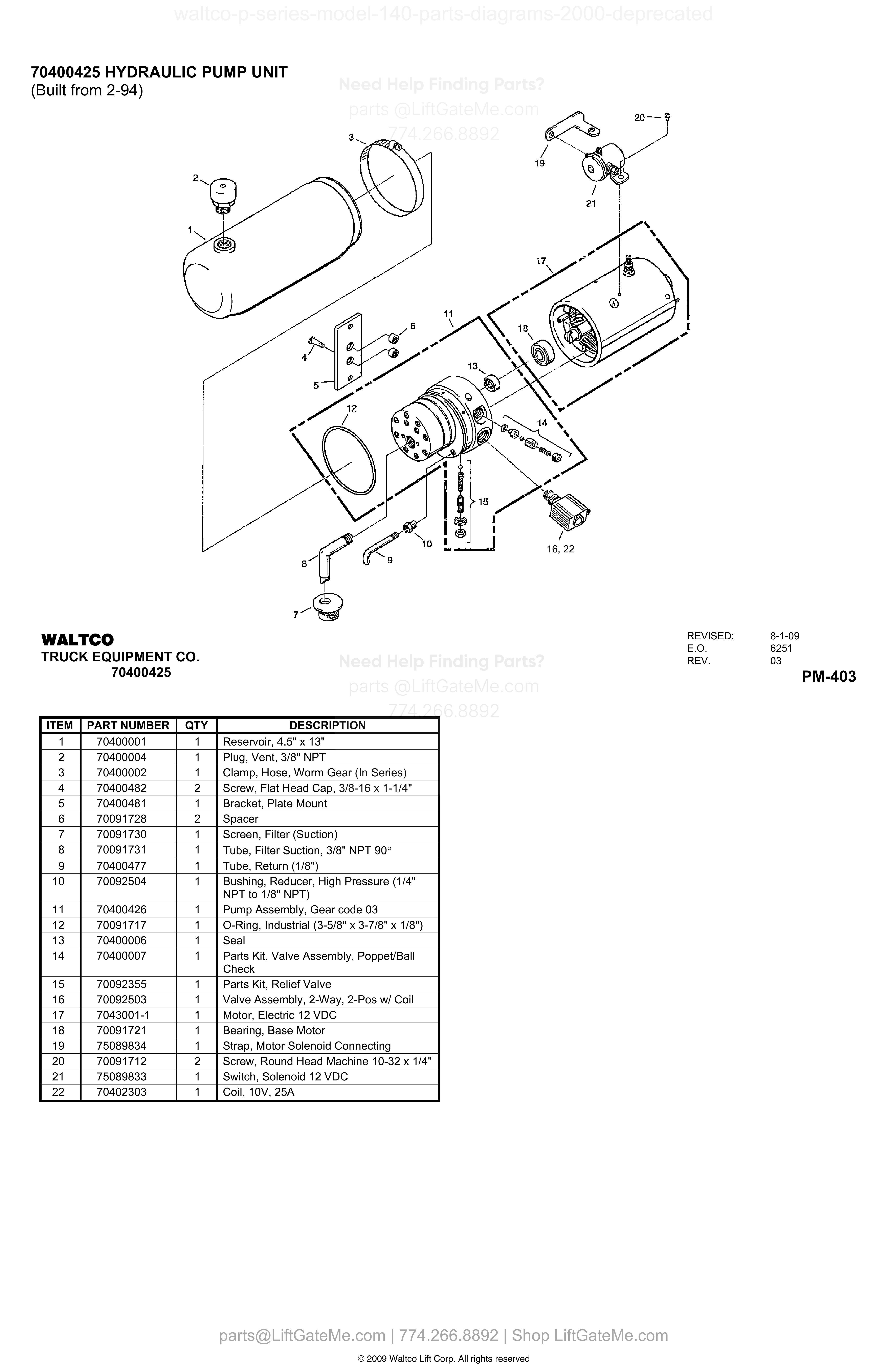
70400425 HYDRAULIC PUMP UNIT
| Item | Qty | Part Number | Description | Actions |
|---|---|---|---|---|
| 1 | 1 | 70400001 | Reservoir, 4.5" x 13" | |
| 2 | 1 | 70400004 | Plug, Vent, 3/8" NPT | |
| 3 | 1 | 70400002 | Clamp, Hose, Worm Gear (In Series) | |
| 4 | 2 | 70400482 | Screw, Flat Head Cap, 3/8-16 x 1-1/4" | |
| 5 | 1 | 70400481 | Bracket, Plate Mount | |
| 6 | 2 | 70091728 | Spacer | |
| 7 | 1 | 70091730 | Screen, Filter (Suction) | |
| 8 | 1 | 70091731 | Tube, Filter Suction, 3/8" NPT 90° | |
| 9 | 1 | 70400477 | Tube, Return (1/8") | |
| 10 | 1 | 70092504 | Bushing, Reducer, High Pressure (1/4" NPT to 1/8" NPT) | |
| 11 | 1 | 70400426 | Pump Assembly, Gear code 03 | |
| 12 | 1 | 70091717 | O-Ring, Industrial (3-5/8" x 3-7/8" x 1/8") | |
| 13 | 1 | 70400006 | Seal | |
| 14 | 1 | 70400007 | Parts Kit, Valve Assembly, Poppet/Ball Check | |
| 15 | 1 | 70092355 | Parts Kit, Relief Valve | |
| 16 | 1 | 70092503 | Valve Assembly, 2-Way, 2-Pos w/ Coil | |
| 17 | 1 | 7043001-1 | Motor, Electric 12 VDC | |
| 18 | 1 | 70091721 | Bearing, Base Motor | |
| 19 | 1 | 75089834 | Strap, Motor Solenoid Connecting | |
| 20 | 2 | 70091712 | Screw, Round Head Machine 10-32 x 1/4" | |
| 21 | 1 | 75089833 | Switch, Solenoid 12 VDC | |
| 22 | 1 | 70402303 | Coil, 10V, 25A |
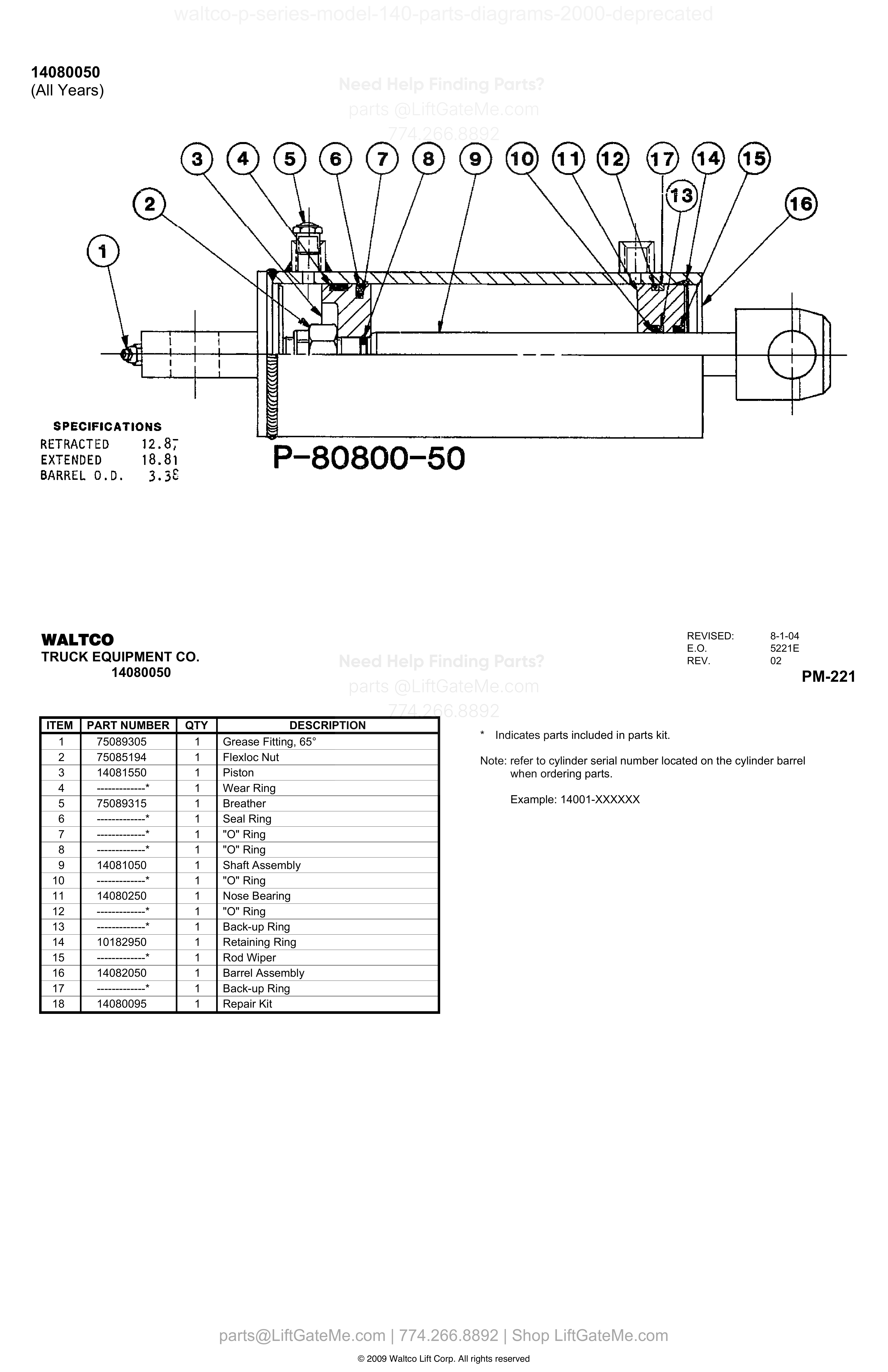
14080050
| Item | Qty | Part Number | Description | Actions |
|---|---|---|---|---|
| 1 | 1 | 75089305 | Grease Fitting, 65° | |
| 2 | 1 | 75085194 | Flexloc Nut | |
| 3 | 1 | 14081550 | Piston | |
| 4 | 1 | -------------* | Wear Ring | |
| 5 | 1 | 75089315 | Breather | |
| 6 | 1 | -------------* | Seal Ring | |
| 7 | 1 | -------------* | "O" Ring | |
| 8 | 1 | -------------* | "O" Ring | |
| 9 | 1 | 14081050 | Shaft Assembly | |
| 10 | 1 | -------------* | "O" Ring | |
| 11 | 1 | 14080250 | Nose Bearing | |
| 12 | 1 | -------------* | "O" Ring | |
| 13 | 1 | -------------* | Back-up Ring | |
| 14 | 1 | 10182950 | Retaining Ring | |
| 15 | 1 | -------------* | Rod Wiper | |
| 16 | 1 | 14082050 | Barrel Assembly | |
| 17 | 1 | -------------* | Back-up Ring | |
| 18 | 1 | 14080095 | Repair Kit |
Need help confirming the correct part?
Share model, serial, and item number.
Fast technical support
Use this after reviewing the diagram and table. We can verify compatibility before purchase.
Phone
(774) 266-8892Send your details and we will help identify the right replacement part.
Contact SupportImportant Diagram Notice
These diagrams are for reference only.
- Due to unintended occasional data alignment issues, a page table may differ slightly from the original OEM PDF.
- Please verify details against the original PDF file.
- Contact our team anytime for part number confirmation.
Reference mismatch detected