
Waltco C-Series Models 221/222 Liftgate Parts Diagrams | Approximate Years Pre-2000
Legacy Waltco C-Series Models 221/222 Tuck-Under parts diagrams
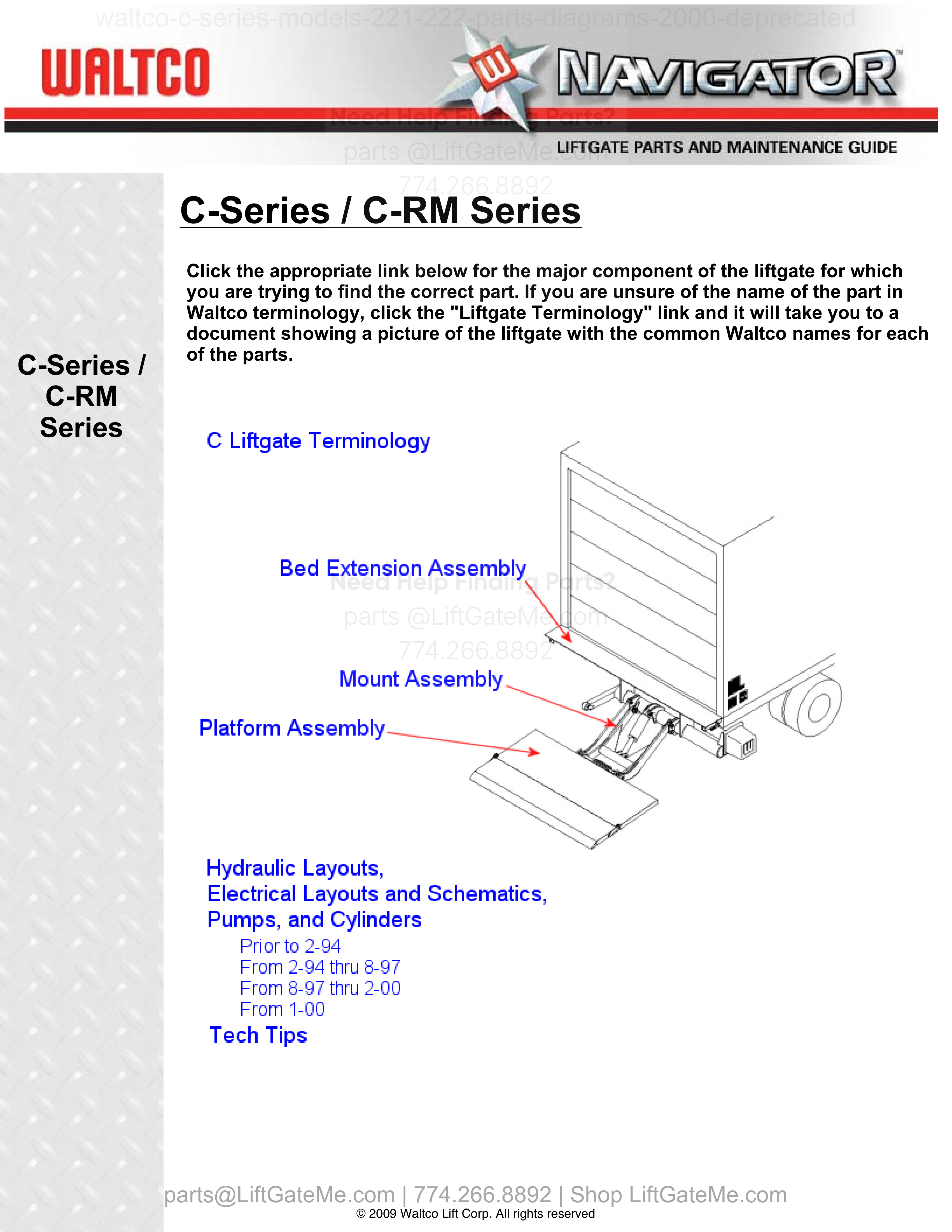
Review Waltco C-Series Models 221/222 parts breakdowns for older pre-2000 tuck-under units. This page helps identify liftgate components and confirm the right OEM replacement parts.
Compatibility and Purchasing Notice
Although the information on this page is taken from an OEM lift gate manual, if you're unsure whether this data matches your exact model and year, PLEASE contact our team. Part numbers can vary by year - even within the same model - and we're always happy to confirm the correct parts for you.
Have your liftgate serial number ready for faster assistance. Where to find it
i


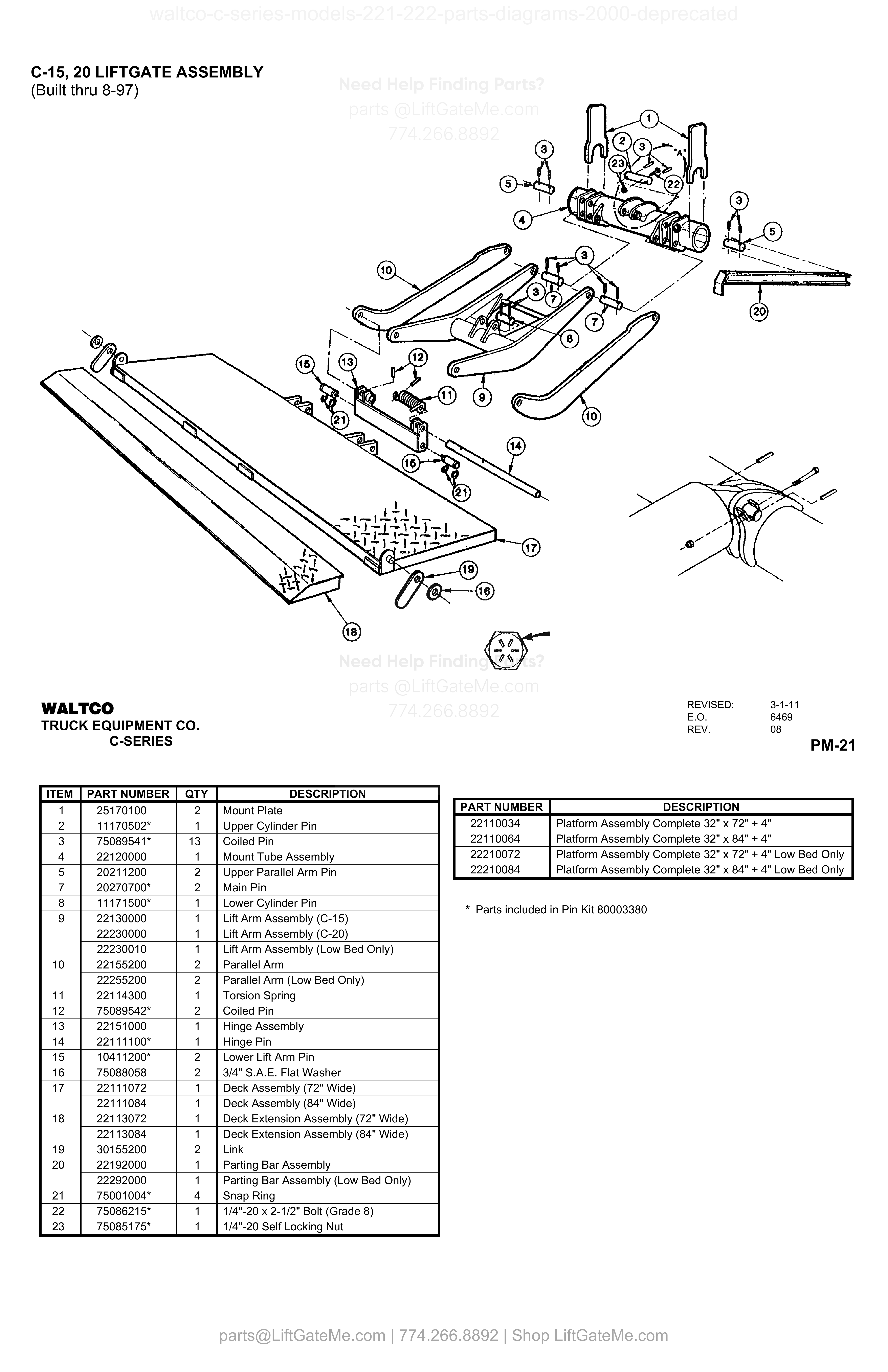
C-15, 20 LIFTGATE ASSEMBLY
| Item | Qty | Part Number | Description | Actions |
|---|---|---|---|---|
| 1 | 2 | 25170100 | Mount Plate | |
| 2 | 1 | 11170502* | Upper Cylinder Pin | |
| 3 | 13 | 75089541* | Coiled Pin | |
| 4 | 1 | 22120000 | Mount Tube Assembly | |
| 5 | 2 | 20211200 | Upper Parallel Arm Pin | |
| 7 | 2 | 20270700* | Main Pin | |
| 8 | 1 | 11171500* | Lower Cylinder Pin | |
| 9 | 1 | 22130000 | Lift Arm Assembly (C-15) | |
| 9 | 1 | 22230000 | Lift Arm Assembly (C-20) | |
| 9 | 1 | 22230010 | Lift Arm Assembly (Low Bed Only) | |
| 10 | 2 | 22155200 | Parallel Arm | |
| 10 | 2 | 22255200 | Parallel Arm (Low Bed Only) | |
| 11 | 1 | 22114300 | Torsion Spring | |
| 12 | 2 | 75089542* | Coiled Pin | |
| 13 | 1 | 22151000 | Hinge Assembly | |
| 14 | 1 | 22111100* | Hinge Pin | |
| 15 | 2 | 10411200* | Lower Lift Arm Pin | |
| 16 | 2 | 75088058 | 3/4" S.A.E. Flat Washer | |
| 17 | 1 | 22111072 | Deck Assembly (72" Wide) | |
| 17 | 1 | 22111084 | Deck Assembly (84" Wide) | |
| 18 | 1 | 22113072 | Deck Extension Assembly (72" Wide) | |
| 18 | 1 | 22113084 | Deck Extension Assembly (84" Wide) | |
| 19 | 2 | 30155200 | Link | |
| 20 | 1 | 22192000 | Parting Bar Assembly | |
| 20 | 1 | 22292000 | Parting Bar Assembly (Low Bed Only) | |
| 21 | 4 | 75001004* | Snap Ring | |
| 22 | 1 | 75086215* | 1/4"-20 x 2-1/2" Bolt (Grade 8) | |
| 23 | 1 | 75085175* | 1/4"-20 Self Locking Nut |
Reference Notice
Manual links are provided for reference only. If you have any doubt, contact us — we’re happy to verify parts and help you purchase with confidence.
Have your liftgate serial number ready for faster assistance. Where to find it
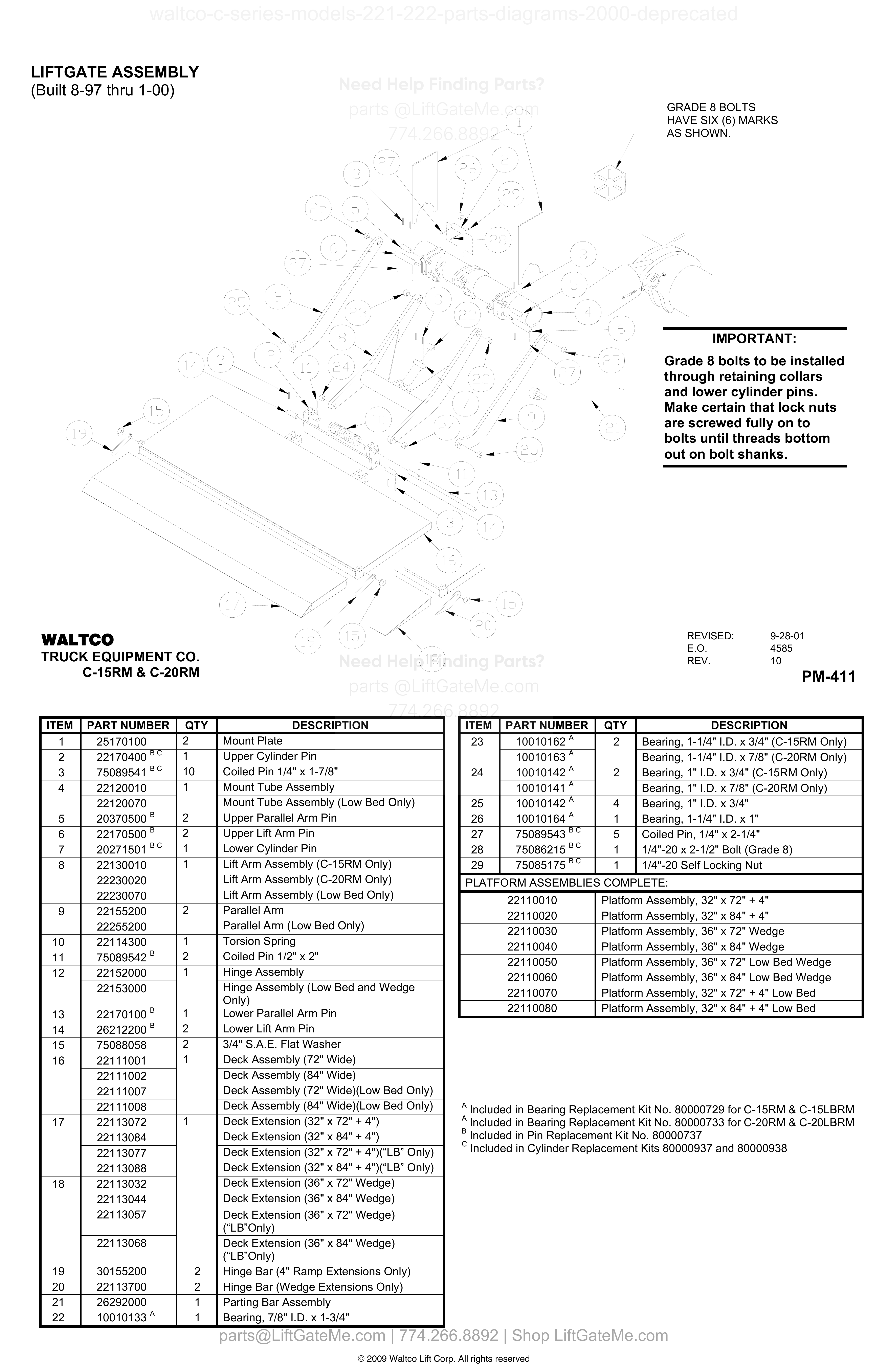
LIFTGATE ASSEMBLY
| Item | Qty | Part Number | Description | Actions |
|---|---|---|---|---|
| 1 | 2 | 25170100 | Mount Plate | |
| 2 | 1 | 22170400 B,C | Upper Cylinder Pin | |
| 3 | 10 | 75089541 B,C | Coiled Pin 1/4" x 1-7/8" | |
| 4 | 1 | 22120010 | Mount Tube Assembly | |
| 4 | 22120070 | Mount Tube Assembly (Low Bed Only) | ||
| 5 | 2 | 20370500 B | Upper Parallel Arm Pin | |
| 6 | 2 | 22170500 B | Upper Lift Arm Pin | |
| 7 | 1 | 20271501 B,C | Lower Cylinder Pin | |
| 8 | 1 | 22130010 | Lift Arm Assembly (C-15RM Only) | |
| 8 | 22230020 | Lift Arm Assembly (C-20RM Only) | ||
| 8 | 22230070 | Lift Arm Assembly (Low Bed Only) | ||
| 9 | 2 | 22155200 | Parallel Arm | |
| 9 | 22255200 | Parallel Arm (Low Bed Only) | ||
| 10 | 1 | 22114300 | Torsion Spring | |
| 11 | 2 | 75089542 B | Coiled Pin 1/2" x 2" | |
| 12 | 1 | 22152000 | Hinge Assembly | |
| 12 | 22153000 | Hinge Assembly (Low Bed and Wedge Only) | ||
| 13 | 1 | 22170100 B | Lower Parallel Arm Pin | |
| 14 | 2 | 26212200 B | Lower Lift Arm Pin | |
| 15 | 2 | 75088058 | 3/4" S.A.E. Flat Washer | |
| 16 | 1 | 22111001 | Deck Assembly (72" Wide) | |
| 16 | 22111002 | Deck Assembly (84" Wide) | ||
| 16 | 22111007 | Deck Assembly (72" Wide)(Low Bed Only) | ||
| 16 | 22111008 | Deck Assembly (84" Wide)(Low Bed Only) | ||
| 17 | 1 | 22113072 | Deck Extension (32" x 72" + 4") | |
| 17 | 22113084 | Deck Extension (32" x 84" + 4") | ||
| 17 | 22113077 | Deck Extension (32" x 72" + 4")(“LB” Only) | ||
| 17 | 22113088 | Deck Extension (32" x 84" + 4")(“LB” Only) | ||
| 18 | 22113032 | Deck Extension (36" x 72" Wedge) | ||
| 18 | 22113044 | Deck Extension (36" x 84" Wedge) | ||
| 18 | 22113057 | Deck Extension (36" x 72" Wedge)(“LB”Only) | ||
| 18 | 22113068 | Deck Extension (36" x 84" Wedge)(“LB”Only) | ||
| 19 | 2 | 30155200 | Hinge Bar (4" Ramp Extensions Only) | |
| 20 | 2 | 22113700 | Hinge Bar (Wedge Extensions Only) | |
| 21 | 1 | 26292000 | Parting Bar Assembly | |
| 22 | 1 | 10010133 A | Bearing, 7/8" I.D. x 1-3/4" | |
| 23 | 2 | 10010162 A | Bearing, 1-1/4" I.D. x 3/4" (C-15RM Only) | |
| 23 | 10010163 A | Bearing, 1-1/4" I.D. x 7/8" (C-20RM Only) | ||
| 24 | 2 | 10010142 A | Bearing, 1" I.D. x 3/4" (C-15RM Only) | |
| 24 | 10010141 A | Bearing, 1" I.D. x 7/8" (C-20RM Only) | ||
| 25 | 4 | 10010142 A | Bearing, 1" I.D. x 3/4" | |
| 26 | 1 | 10010164 A | Bearing, 1-1/4" I.D. x 1" | |
| 27 | 5 | 75089543 B,C | Coiled Pin, 1/4" x 2-1/4" | |
| 28 | 1 | 75086215 B,C | 1/4"-20 x 2-1/2" Bolt (Grade 8) | |
| 29 | 1 | 75085175 B,C | 1/4"-20 Self Locking Nut |
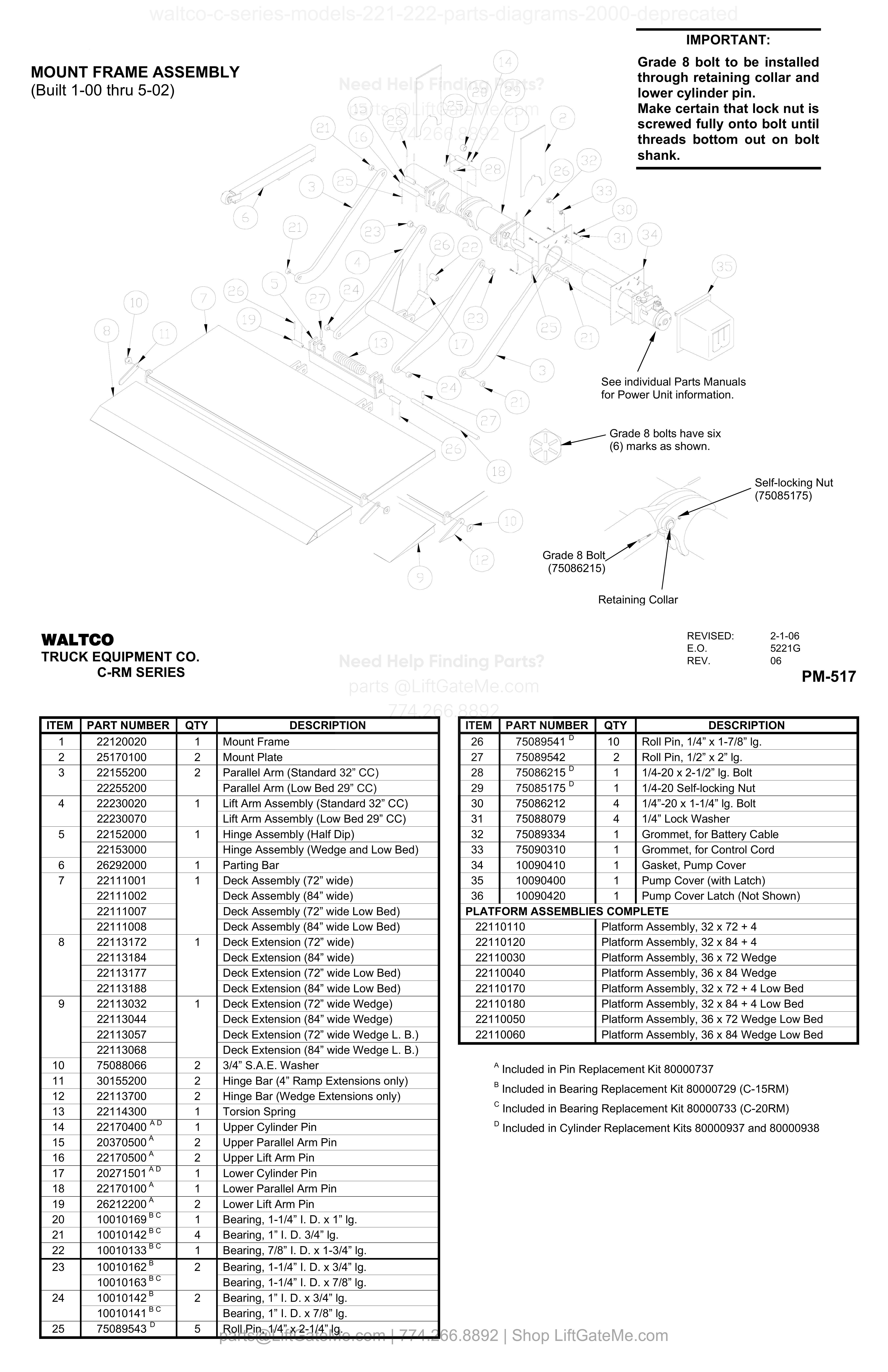
MOUNT FRAME ASSEMBLY (Built 1-00 thru 5-02)
| Item | Qty | Part Number | Description | Actions |
|---|---|---|---|---|
| 1 | 1 | 22120020 | Mount Frame | |
| 2 | 2 | 25170100 | Mount Plate | |
| 3 | 2 | 22155200 | Parallel Arm (Standard 32” CC) | |
| 3 | 22255200 | Parallel Arm (Low Bed 29” CC) | ||
| 4 | 1 | 22230020 | Lift Arm Assembly (Standard 32” CC) | |
| 4 | 22230070 | Lift Arm Assembly (Low Bed 29” CC) | ||
| 5 | 1 | 22152000 | Hinge Assembly (Half Dip) | |
| 5 | 22153000 | Hinge Assembly (Wedge and Low Bed) | ||
| 6 | 1 | 26292000 | Parting Bar | |
| 7 | 1 | 22111001 | Deck Assembly (72” wide) | |
| 7 | 22111002 | Deck Assembly (84” wide) | ||
| 7 | 22111007 | Deck Assembly (72” wide Low Bed) | ||
| 7 | 22111008 | Deck Assembly (84” wide Low Bed) | ||
| 8 | 1 | 22113172 | Deck Extension (72” wide) | |
| 8 | 22113184 | Deck Extension (84” wide) | ||
| 8 | 22113177 | Deck Extension (72” wide Low Bed) | ||
| 8 | 22113188 | Deck Extension (84” wide Low Bed) | ||
| 9 | 1 | 22113032 | Deck Extension (72” wide Wedge) | |
| 9 | 22113044 | Deck Extension (84” wide Wedge) | ||
| 9 | 22113057 | Deck Extension (72” wide Wedge L. B.) | ||
| 9 | 22113068 | Deck Extension (84” wide Wedge L. B.) | ||
| 10 | 2 | 75088066 | 3/4” S.A.E. Washer | |
| 11 | 2 | 30155200 | Hinge Bar (4” Ramp Extensions only) | |
| 12 | 2 | 22113700 | Hinge Bar (Wedge Extensions only) | |
| 13 | 1 | 22114300 | Torsion Spring | |
| 14 | 1 | 22170400 A,D | Upper Cylinder Pin | |
| 15 | 2 | 20370500 A | Upper Parallel Arm Pin | |
| 16 | 2 | 22170500 A | Upper Lift Arm Pin | |
| 17 | 1 | 20271501 A,D | Lower Cylinder Pin | |
| 18 | 1 | 22170100 A | Lower Parallel Arm Pin | |
| 19 | 2 | 26212200 A | Lower Lift Arm Pin | |
| 20 | 1 | 10010169 B,C | Bearing, 1-1/4” I. D. x 1” lg. | |
| 21 | 4 | 10010142 B,C | Bearing, 1” I. D. 3/4” lg. | |
| 22 | 1 | 10010133 B,C | Bearing, 7/8” I. D. x 1-3/4” lg. | |
| 23 | 2 | 10010162 B | Bearing, 1-1/4” I. D. x 3/4” lg. | |
| 23 | 10010163 B,C | Bearing, 1-1/4” I. D. x 7/8” lg. | ||
| 24 | 2 | 10010142 B | Bearing, 1” I. D. x 3/4” lg. | |
| 24 | 10010141 B,C | Bearing, 1” I. D. x 7/8” lg. | ||
| 25 | 5 | 75089543 D | Roll Pin, 1/4” x 2-1/4” lg. | |
| 26 | 10 | 75089541 D | Roll Pin, 1/4” x 1-7/8” lg. | |
| 27 | 2 | 75089542 | Roll Pin, 1/2” x 2” lg. | |
| 28 | 1 | 75086215 D | 1/4-20 x 2-1/2” lg. Bolt | |
| 29 | 1 | 75085175 D | 1/4-20 Self-locking Nut | |
| 30 | 4 | 75086212 | 1/4”-20 x 1-1/4” lg. Bolt | |
| 31 | 4 | 75088079 | 1/4” Lock Washer | |
| 32 | 1 | 75089334 | Grommet, for Battery Cable | |
| 33 | 1 | 75090310 | Grommet, for Control Cord | |
| 34 | 1 | 10090410 | Gasket, Pump Cover | |
| 35 | 1 | 10090400 | Pump Cover (with Latch) | |
| 36 | 1 | 10090420 | Pump Cover Latch (Not Shown) | |
| 22110110 | Platform Assembly, 32 x 72 + 4 | |||
| 22110120 | Platform Assembly, 32 x 84 + 4 | |||
| 22110030 | Platform Assembly, 36 x 72 Wedge | |||
| 22110040 | Platform Assembly, 36 x 84 Wedge | |||
| 22110170 | Platform Assembly, 32 x 72 + 4 Low Bed | |||
| 22110180 | Platform Assembly, 32 x 84 + 4 Low Bed | |||
| 22110050 | Platform Assembly, 36 x 72 Wedge Low Bed | |||
| 22110060 | Platform Assembly, 36 x 84 Wedge Low Bed |
Reference Notice
Manual links are provided for reference only. If you have any doubt, contact us — we’re happy to verify parts and help you purchase with confidence.
Have your liftgate serial number ready for faster assistance. Where to find it
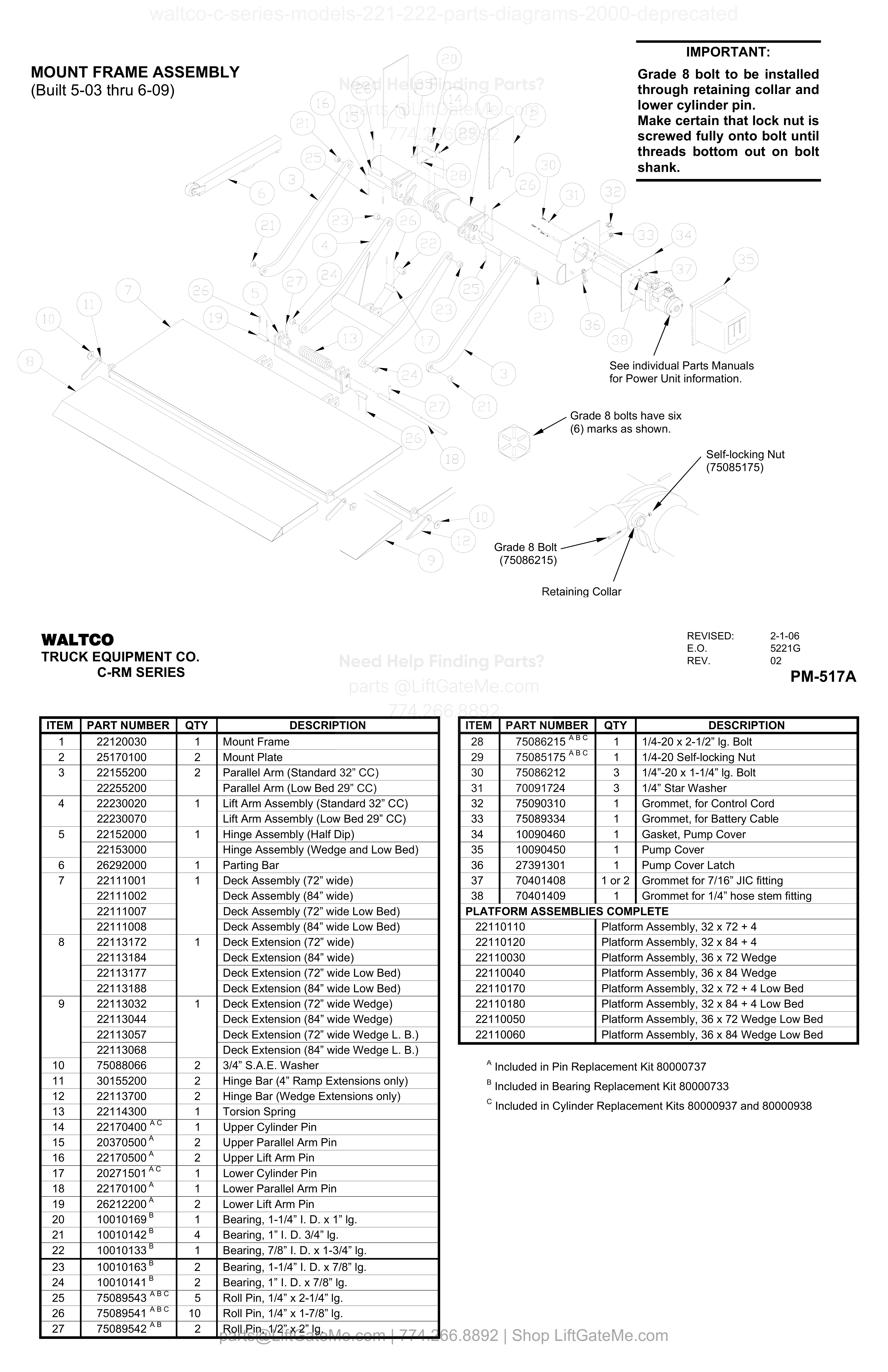
MOUNT FRAME ASSEMBLY (Built 5-03 thru 6-09)
| Item | Qty | Part Number | Description | Actions |
|---|---|---|---|---|
| 1 | 1 | 22120030 | Mount Frame | |
| 2 | 2 | 25170100 | Mount Plate | |
| 3 | 2 | 22155200 | Parallel Arm (Standard 32” CC) | |
| 3 | 22255200 | Parallel Arm (Low Bed 29” CC) | ||
| 4 | 1 | 22230020 | Lift Arm Assembly (Standard 32” CC) | |
| 4 | 22230070 | Lift Arm Assembly (Low Bed 29” CC) | ||
| 5 | 1 | 22152000 | Hinge Assembly (Half Dip) | |
| 5 | 22153000 | Hinge Assembly (Wedge and Low Bed) | ||
| 6 | 1 | 26292000 | Parting Bar | |
| 7 | 1 | 22111001 | Deck Assembly (72” wide) | |
| 7 | 22111002 | Deck Assembly (84” wide) | ||
| 7 | 22111007 | Deck Assembly (72” wide Low Bed) | ||
| 7 | 22111008 | Deck Assembly (84” wide Low Bed) | ||
| 8 | 1 | 22113172 | Deck Extension (72” wide) | |
| 8 | 22113184 | Deck Extension (84” wide) | ||
| 8 | 22113177 | Deck Extension (72” wide Low Bed) | ||
| 8 | 22113188 | Deck Extension (84” wide Low Bed) | ||
| 9 | 1 | 22113032 | Deck Extension (72” wide Wedge) | |
| 9 | 22113044 | Deck Extension (84” wide Wedge) | ||
| 9 | 22113057 | Deck Extension (72” wide Wedge L. B.) | ||
| 9 | 22113068 | Deck Extension (84” wide Wedge L. B.) | ||
| 10 | 2 | 75088066 | 3/4” S.A.E. Washer | |
| 11 | 2 | 30155200 | Hinge Bar (4” Ramp Extensions only) | |
| 12 | 2 | 22113700 | Hinge Bar (Wedge Extensions only) | |
| 13 | 1 | 22114300 | Torsion Spring | |
| 14 | 1 | 22170400 A,C | Upper Cylinder Pin | |
| 15 | 2 | 20370500 A | Upper Parallel Arm Pin | |
| 16 | 2 | 22170500 A | Upper Lift Arm Pin | |
| 17 | 1 | 20271501 A,C | Lower Cylinder Pin | |
| 18 | 1 | 22170100 A | Lower Parallel Arm Pin | |
| 19 | 2 | 26212200 A | Lower Lift Arm Pin | |
| 20 | 1 | 10010169 B | Bearing, 1-1/4” I. D. x 1” lg. | |
| 21 | 4 | 10010142 B | Bearing, 1” I. D. 3/4” lg. | |
| 22 | 1 | 10010133 B | Bearing, 7/8” I. D. x 1-3/4” lg. | |
| 23 | 2 | 10010163 B | Bearing, 1-1/4” I. D. x 7/8” lg. | |
| 24 | 2 | 10010141 B | Bearing, 1” I. D. x 7/8” lg. | |
| 25 | 5 | 75089543^A,B,C | Roll Pin, 1/4” x 2-1/4” lg. | |
| 26 | 10 | 75089541^A,B,C | Roll Pin, 1/4” x 1-7/8” lg. | |
| 27 | 2 | 75089542 A,B | Roll Pin, 1/2” x 2” lg. | |
| 28 | 1 | 75086215^A,B,C | 1/4-20 x 2-1/2” lg. Bolt | |
| 29 | 1 | 75085175^A,B,C | 1/4-20 Self-locking Nut | |
| 30 | 3 | 75086212 | 1/4”-20 x 1-1/4” lg. Bolt | |
| 31 | 3 | 70091724 | 1/4” Star Washer | |
| 32 | 1 | 75090310 | Grommet, for Control Cord | |
| 33 | 1 | 75089334 | Grommet, for Battery Cable | |
| 34 | 1 | 10090460 | Gasket, Pump Cover | |
| 35 | 1 | 10090450 | Pump Cover | |
| 36 | 1 | 27391301 | Pump Cover Latch | |
| 37 | 1 or 2 | 70401408 | Grommet for 7/16” JIC fitting | |
| 38 | 1 | 70401409 | Grommet for 1/4” hose stem fitting | |
| 22110110 | Platform Assembly, 32 x 72 + 4 | |||
| 22110120 | Platform Assembly, 32 x 84 + 4 | |||
| 22110030 | Platform Assembly, 36 x 72 Wedge | |||
| 22110040 | Platform Assembly, 36 x 84 Wedge | |||
| 22110170 | Platform Assembly, 32 x 72 + 4 Low Bed | |||
| 22110180 | Platform Assembly, 32 x 84 + 4 Low Bed | |||
| 22110050 | Platform Assembly, 36 x 72 Wedge Low Bed | |||
| 22110060 | Platform Assembly, 36 x 84 Wedge Low Bed |
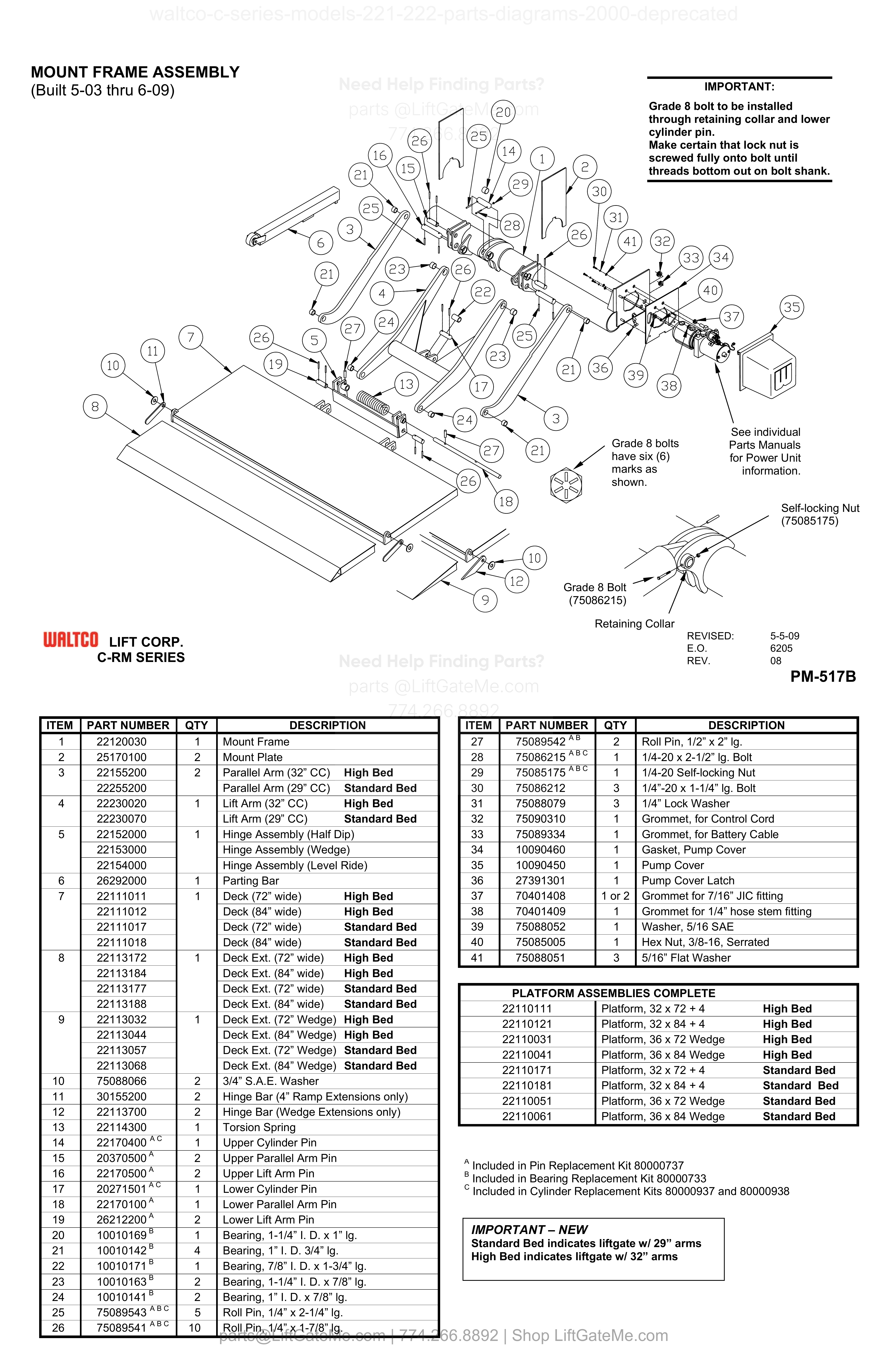
MOUNT FRAME ASSEMBLY
| Item | Qty | Part Number | Description | Actions |
|---|---|---|---|---|
| 1 | 1 | 22120030 | Mount Frame | |
| 2 | 2 | 25170100 | Mount Plate | |
| 3 | 2 | 22155200 | Parallel Arm (32” CC) High Bed | |
| 3 | 22255200 | Parallel Arm (29” CC) Standard Bed | ||
| 4 | 1 | 22230020 | Lift Arm (32” CC) High Bed | |
| 4 | 22230070 | Lift Arm (29” CC) Standard Bed | ||
| 5 | 1 | 22152000 | Hinge Assembly (Half Dip) | |
| 5 | 22153000 | Hinge Assembly (Wedge) | ||
| 5 | 22154000 | Hinge Assembly (Level Ride) | ||
| 6 | 1 | 26292000 | Parting Bar | |
| 7 | 1 | 22111011 | Deck (72” wide) High Bed | |
| 7 | 22111012 | Deck (84” wide) High Bed | ||
| 7 | 22111017 | Deck (72” wide) Standard Bed | ||
| 7 | 22111018 | Deck (84” wide) Standard Bed | ||
| 8 | 1 | 22113172 | Deck Ext. (72” wide) High Bed | |
| 8 | 22113184 | Deck Ext. (84” wide) High Bed | ||
| 8 | 22113177 | Deck Ext. (72” wide) Standard Bed | ||
| 8 | 22113188 | Deck Ext. (84” wide) Standard Bed | ||
| 9 | 1 | 22113032 | Deck Ext. (72” Wedge) High Bed | |
| 9 | 22113044 | Deck Ext. (84” Wedge) High Bed | ||
| 9 | 22113057 | Deck Ext. (72” Wedge) Standard Bed | ||
| 9 | 22113068 | Deck Ext. (84” Wedge) Standard Bed | ||
| 10 | 2 | 75088066 | 3/4” S.A.E. Washer | |
| 11 | 2 | 30155200 | Hinge Bar (4” Ramp Extensions only) | |
| 12 | 2 | 22113700 | Hinge Bar (Wedge Extensions only) | |
| 13 | 1 | 22114300 | Torsion Spring | |
| 14 | 1 | 22170400 A,C | Upper Cylinder Pin | |
| 15 | 2 | 20370500 A | Upper Parallel Arm Pin | |
| 16 | 2 | 22170500 A | Upper Lift Arm Pin | |
| 17 | 1 | 20271501 A,C | Lower Cylinder Pin | |
| 18 | 1 | 22170100 A | Lower Parallel Arm Pin | |
| 19 | 2 | 26212200 A | Lower Lift Arm Pin | |
| 20 | 1 | 10010169 B | Bearing, 1-1/4” I. D. x 1” lg. | |
| 21 | 4 | 10010142 B | Bearing, 1” I. D. 3/4” lg. | |
| 22 | 1 | 10010171 B | Bearing, 7/8” I. D. x 1-3/4” lg. | |
| 23 | 2 | 10010163 B | Bearing, 1-1/4” I. D. x 7/8” lg. | |
| 24 | 2 | 10010141^A,B,C | Bearing, 1” I. D. x 7/8” lg. | |
| 25 | 5 | 75089543^A,B,C | Roll Pin, 1/4” x 2-1/4” lg. | |
| 26 | 10 | 75089541^A,B,C | Roll Pin, 1/4” x 1-7/8” lg. | |
| 27 | 2 | 75089542 A,B | Roll Pin, 1/2” x 2” lg. | |
| 28 | 1 | 75086215^A,B,C | 1/4-20 x 2-1/2” lg. Bolt | |
| 29 | 1 | 75085175^A,B,C | 1/4-20 Self-locking Nut | |
| 30 | 3 | 75086212 | 1/4”-20 x 1-1/4” lg. Bolt | |
| 31 | 3 | 75088079 | 1/4” Lock Washer | |
| 32 | 1 | 75090310 | Grommet, for Control Cord | |
| 33 | 1 | 75089334 | Grommet, for Battery Cable | |
| 34 | 1 | 10090460 | Gasket, Pump Cover | |
| 35 | 1 | 10090450 | Pump Cover | |
| 36 | 1 | 27391301 | Pump Cover Latch | |
| 37 | 1 or 2 | 70401408 | Grommet for 7/16” JIC fitting | |
| 38 | 1 | 70401409 | Grommet for 1/4” hose stem fitting | |
| 39 | 1 | 75088052 | Washer, 5/16 SAE | |
| 40 | 1 | 75085005 | Hex Nut, 3/8-16, Serrated | |
| 41 | 3 | 75088051 | 5/16” Flat Washer |
Reference Notice
Manual links are provided for reference only. If you have any doubt, contact us — we’re happy to verify parts and help you purchase with confidence.
Have your liftgate serial number ready for faster assistance. Where to find it
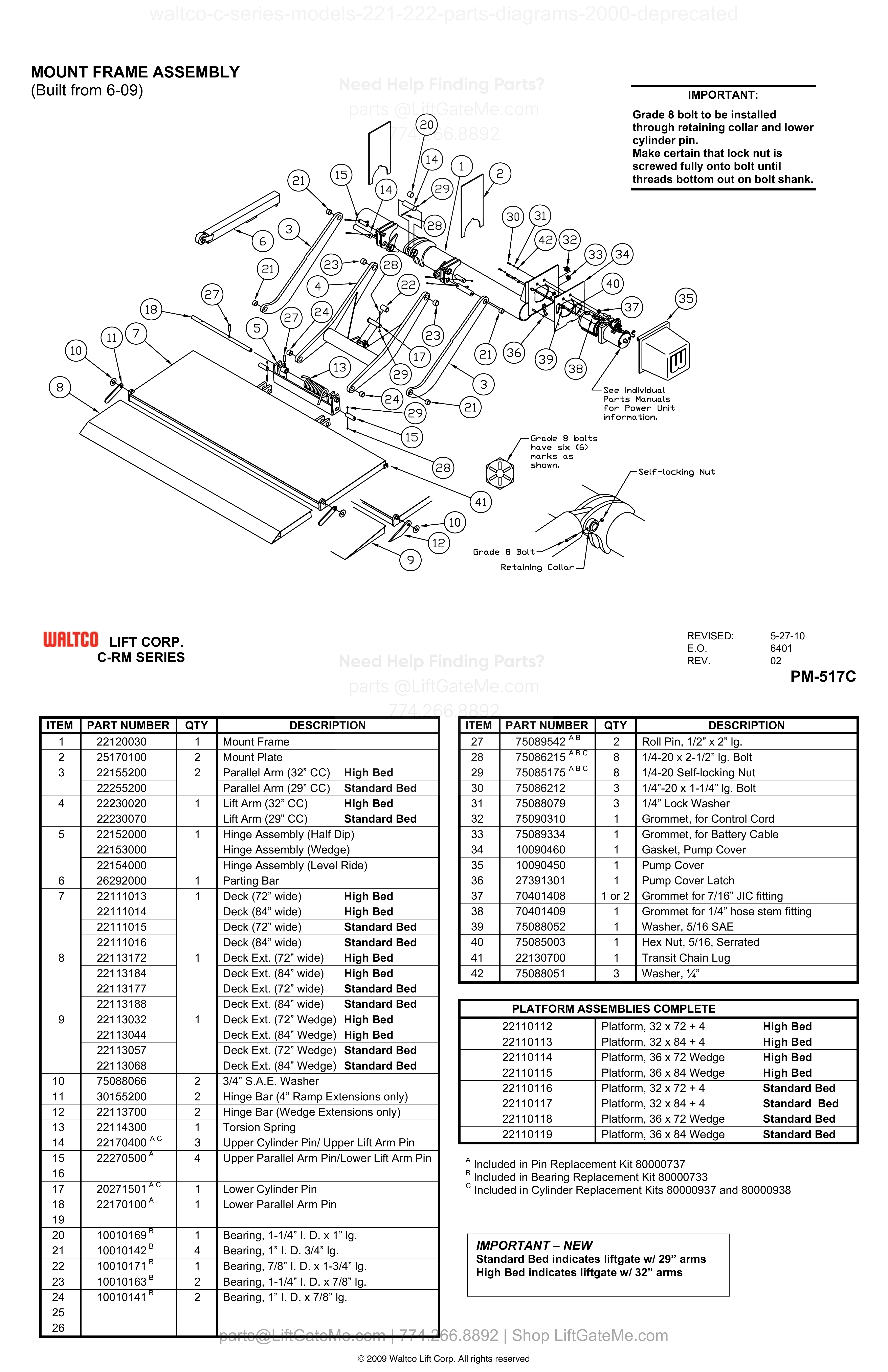
MOUNT FRAME ASSEMBLY (Built from 6-09)
| Item | Qty | Part Number | Description | Actions |
|---|---|---|---|---|
| 1 | 1 | 22120030 | Mount Frame | |
| 2 | 2 | 25170100 | Mount Plate | |
| 3 | 2 | 22155200 | Parallel Arm (32” CC) High Bed | |
| 3 | 22255200 | Parallel Arm (29” CC) Standard Bed | ||
| 4 | 1 | 22230020 | Lift Arm (32” CC) High Bed | |
| 4 | 22230070 | Lift Arm (29” CC) Standard Bed | ||
| 5 | 1 | 22152000 | Hinge Assembly (Half Dip) | |
| 5 | 22153000 | Hinge Assembly (Wedge) | ||
| 5 | 22154000 | Hinge Assembly (Level Ride) | ||
| 6 | 1 | 26292000 | Parting Bar | |
| 7 | 1 | 22111013 | Deck (72” wide) High Bed | |
| 7 | 22111014 | Deck (84” wide) High Bed | ||
| 7 | 22111015 | Deck (72” wide) Standard Bed | ||
| 7 | 22111016 | Deck (84” wide) Standard Bed | ||
| 8 | 1 | 22113172 | Deck Ext. (72” wide) High Bed | |
| 8 | 22113184 | Deck Ext. (84” wide) High Bed | ||
| 8 | 22113177 | Deck Ext. (72” wide) Standard Bed | ||
| 8 | 22113188 | Deck Ext. (84” wide) Standard Bed | ||
| 9 | 1 | 22113032 | Deck Ext. (72” Wedge) High Bed | |
| 9 | 22113044 | Deck Ext. (84” Wedge) High Bed | ||
| 9 | 22113057 | Deck Ext. (72” Wedge) Standard Bed | ||
| 9 | 22113068 | Deck Ext. (84” Wedge) Standard Bed | ||
| 10 | 2 | 75088066 | 3/4” S.A.E. Washer | |
| 11 | 2 | 30155200 | Hinge Bar (4” Ramp Extensions only) | |
| 12 | 2 | 22113700 | Hinge Bar (Wedge Extensions only) | |
| 13 | 1 | 22114300 | Torsion Spring | |
| 14 | 3 | 22170400 A,C | Upper Cylinder Pin/ Upper Lift Arm Pin | |
| 15 | 4 | 22270500 A | Upper Parallel Arm Pin/Lower Lift Arm Pin | |
| 17 | 1 | 20271501 A,C | Lower Cylinder Pin | |
| 18 | 1 | 22170100 A | Lower Parallel Arm Pin | |
| 20 | 1 | 10010169 B | Bearing, 1-1/4” I. D. x 1” lg. | |
| 21 | 4 | 10010142 B | Bearing, 1” I. D. 3/4” lg. | |
| 22 | 1 | 10010171 B | Bearing, 7/8” I. D. x 1-3/4” lg. | |
| 23 | 2 | 10010163 B | Bearing, 1-1/4” I. D. x 7/8” lg. | |
| 24 | 2 | 10010141 B | Bearing, 1” I. D. x 7/8” lg. | |
| 27 | 2 | 75089542 A,B | Roll Pin, 1/2” x 2” lg. | |
| 28 | 8 | 75086215^A,B,C | 1/4-20 x 2-1/2” lg. Bolt | |
| 29 | 8 | 75085175^A,B,C | 1/4-20 Self-locking Nut | |
| 30 | 3 | 75086212 | 1/4”-20 x 1-1/4” lg. Bolt | |
| 31 | 3 | 75088079 | 1/4” Lock Washer | |
| 32 | 1 | 75090310 | Grommet, for Control Cord | |
| 33 | 1 | 75089334 | Grommet, for Battery Cable | |
| 34 | 1 | 10090460 | Gasket, Pump Cover | |
| 35 | 1 | 10090450 | Pump Cover | |
| 36 | 1 | 27391301 | Pump Cover Latch | |
| 37 | 1 or 2 | 70401408 | Grommet for 7/16” JIC fitting | |
| 38 | 1 | 70401409 | Grommet for 1/4” hose stem fitting | |
| 39 | 1 | 75088052 | Washer, 5/16 SAE | |
| 40 | 1 | 75085003 | Hex Nut, 5/16, Serrated | |
| 41 | 1 | 22130700 | Transit Chain Lug | |
| 42 | 3 | 75088051 | Washer, ¼” | |
| 16 | ||||
| 19 | ||||
| 25 | ||||
| 26 |
i

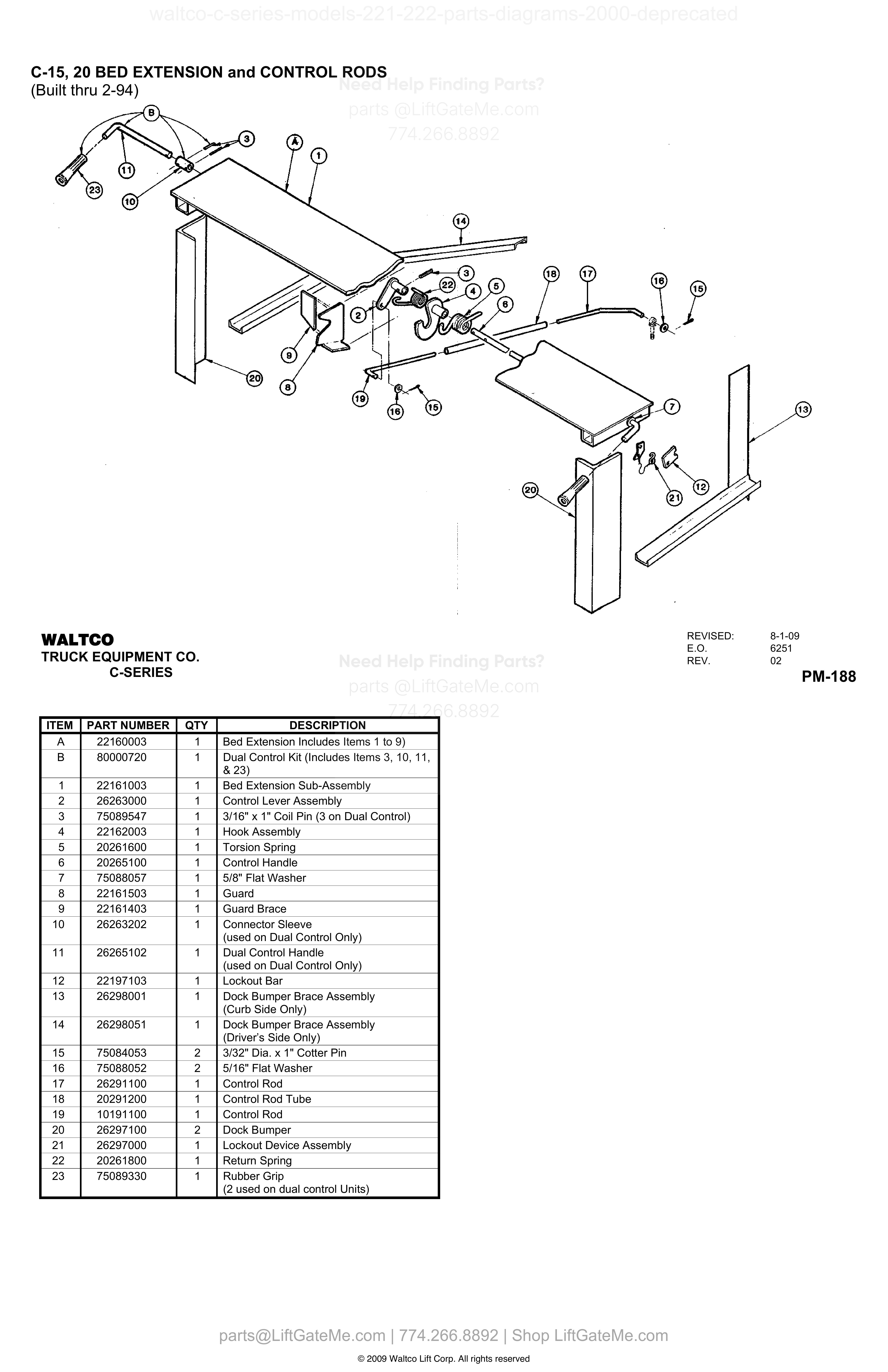
C-15, 20 BED EXTENSION and CONTROL RODS
| Item | Qty | Part Number | Description | Actions |
|---|---|---|---|---|
| A | 1 | 22160003 | Bed Extension Includes Items 1 to 9) | |
| B | 1 | 80000720 | Dual Control Kit (Includes Items 3, 10, 11, & 23) | |
| 1 | 1 | 22161003 | Bed Extension Sub-Assembly | |
| 2 | 1 | 26263000 | Control Lever Assembly | |
| 3 | 1 | 75089547 | 3/16" x 1" Coil Pin (3 on Dual Control) | |
| 4 | 1 | 22162003 | Hook Assembly | |
| 5 | 1 | 20261600 | Torsion Spring | |
| 6 | 1 | 20265100 | Control Handle | |
| 7 | 1 | 75088057 | 5/8" Flat Washer | |
| 8 | 1 | 22161503 | Guard | |
| 9 | 1 | 22161403 | Guard Brace | |
| 10 | 1 | 26263202 | Connector Sleeve (used on Dual Control Only) | |
| 11 | 1 | 26265102 | Dual Control Handle (used on Dual Control Only) | |
| 12 | 1 | 22197103 | Lockout Bar | |
| 13 | 1 | 26298001 | Dock Bumper Brace Assembly (Curb Side Only) | |
| 14 | 1 | 26298051 | Dock Bumper Brace Assembly (Driver’s Side Only) | |
| 15 | 2 | 75084053 | 3/32" Dia. x 1" Cotter Pin | |
| 16 | 2 | 75088052 | 5/16" Flat Washer | |
| 17 | 1 | 26291100 | Control Rod | |
| 18 | 1 | 20291200 | Control Rod Tube | |
| 19 | 1 | 10191100 | Control Rod | |
| 20 | 2 | 26297100 | Dock Bumper | |
| 21 | 1 | 26297000 | Lockout Device Assembly | |
| 22 | 1 | 20261800 | Return Spring | |
| 23 | 1 | 75089330 | Rubber Grip (2 used on dual control Units) |
Reference Notice
Manual links are provided for reference only. If you have any doubt, contact us — we’re happy to verify parts and help you purchase with confidence.
Have your liftgate serial number ready for faster assistance. Where to find it
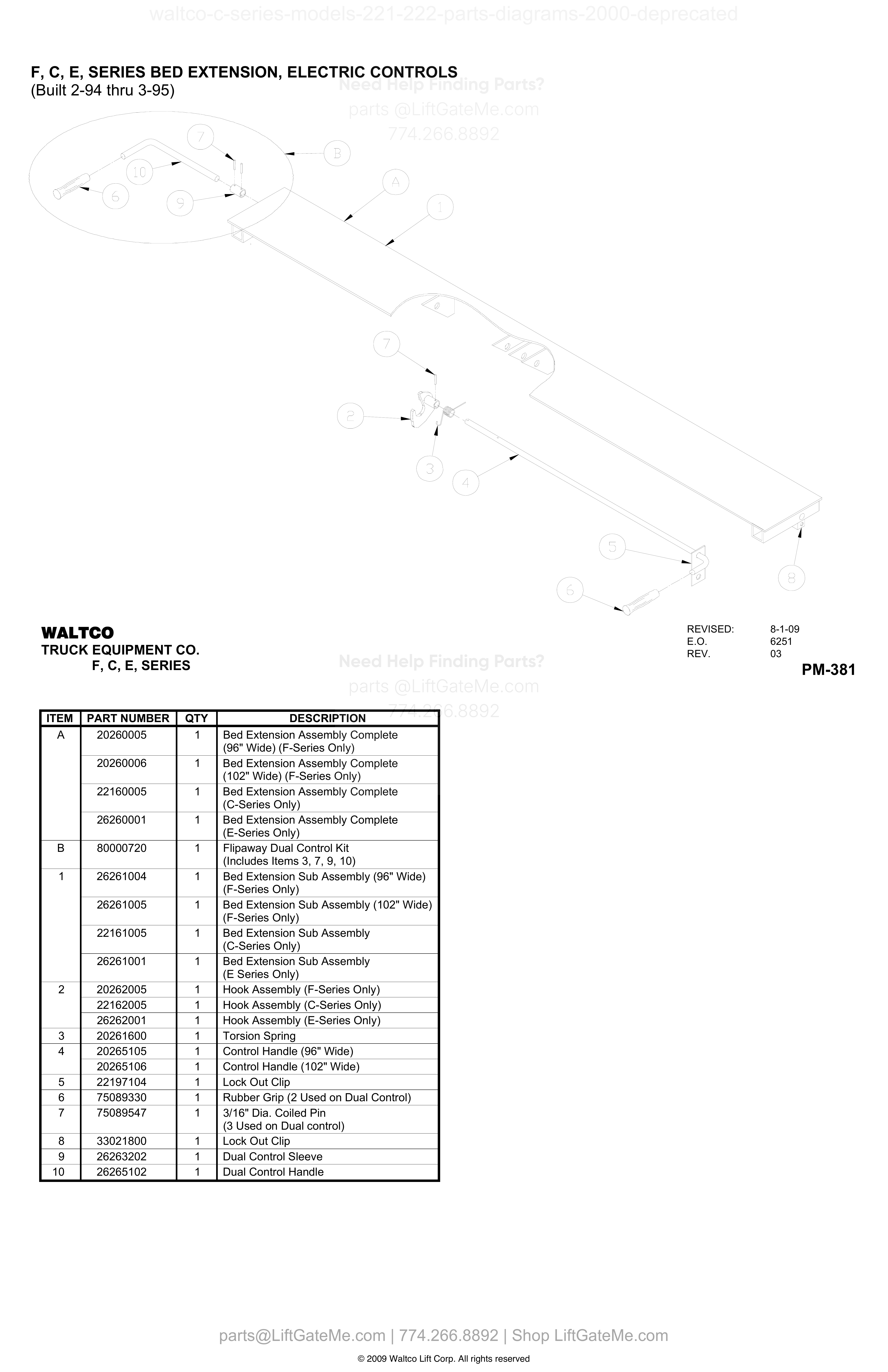
F, C, E, SERIES BED EXTENSION, ELECTRIC CONTROLS (Built 2-94 thru 3-95)
| Item | Qty | Part Number | Description | Actions |
|---|---|---|---|---|
| A | 1 | 20260005 | Bed Extension Assembly Complete (96" Wide) (F-Series Only) | |
| A | 1 | 20260006 | Bed Extension Assembly Complete (102" Wide) (F-Series Only) | |
| A | 1 | 22160005 | Bed Extension Assembly Complete (C-Series Only) | |
| A | 1 | 26260001 | Bed Extension Assembly Complete (E-Series Only) | |
| B | 1 | 80000720 | Flipaway Dual Control Kit (Includes Items 3, 7, 9, 10) | |
| 1 | 1 | 26261004 | Bed Extension Sub Assembly (96" Wide) (F-Series Only) | |
| 1 | 1 | 26261005 | Bed Extension Sub Assembly (102" Wide) (F-Series Only) | |
| 1 | 1 | 22161005 | Bed Extension Sub Assembly (C-Series Only) | |
| 1 | 1 | 26261001 | Bed Extension Sub Assembly (E Series Only) | |
| 2 | 1 | 20262005 | Hook Assembly (F-Series Only) | |
| 2 | 1 | 22162005 | Hook Assembly (C-Series Only) | |
| 2 | 1 | 26262001 | Hook Assembly (E-Series Only) | |
| 3 | 1 | 20261600 | Torsion Spring | |
| 4 | 1 | 20265105 | Control Handle (96" Wide) | |
| 4 | 1 | 20265106 | Control Handle (102" Wide) | |
| 5 | 1 | 22197104 | Lock Out Clip | |
| 6 | 1 | 75089330 | Rubber Grip (2 Used on Dual Control) | |
| 7 | 1 | 75089547 | 3/16" Dia. Coiled Pin (3 Used on Dual control) | |
| 8 | 1 | 33021800 | Lock Out Clip | |
| 9 | 1 | 26263202 | Dual Control Sleeve | |
| 10 | 1 | 26265102 | Dual Control Handle |
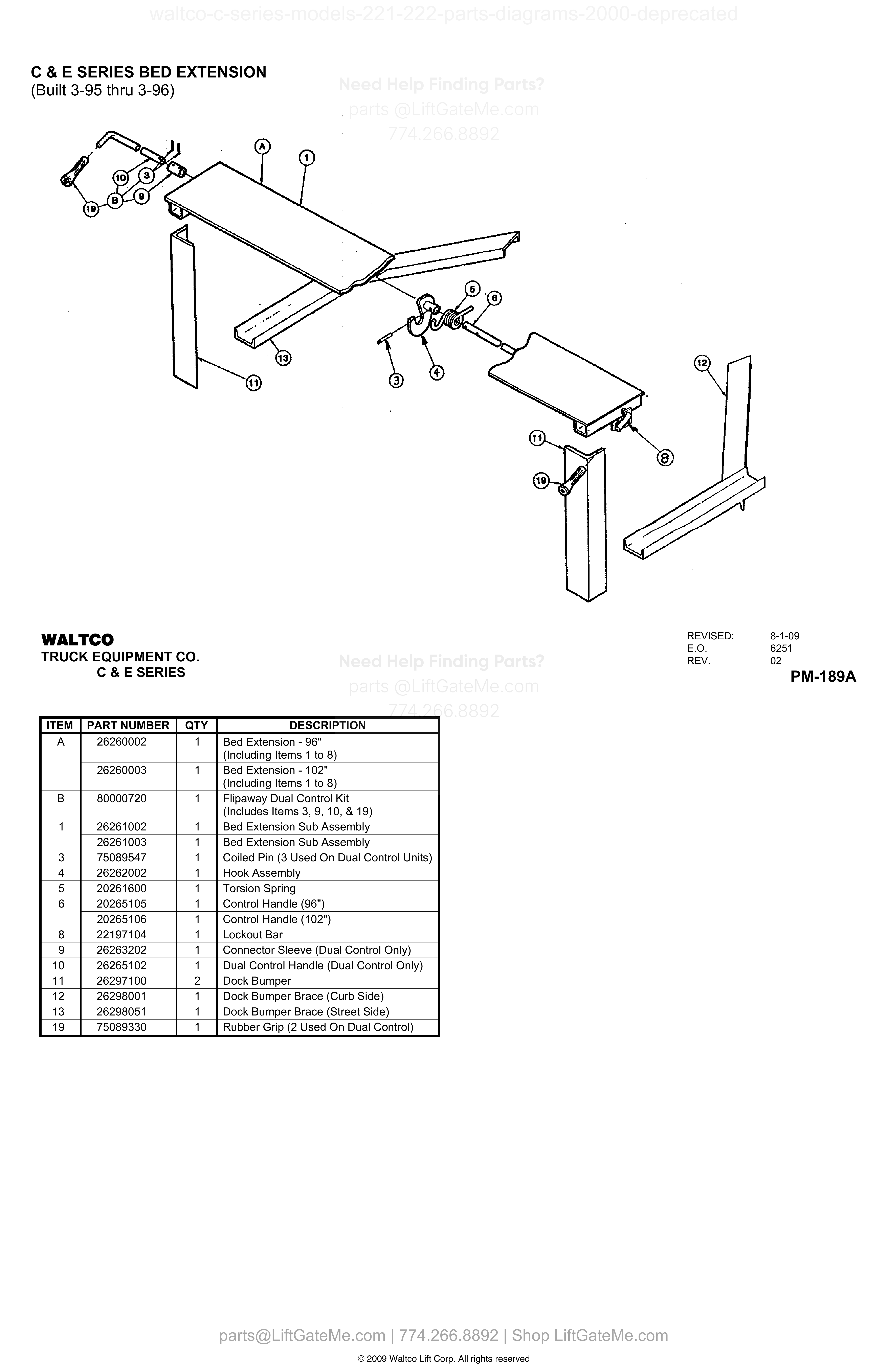
C & E SERIES BED EXTENSION
| Item | Qty | Part Number | Description | Actions |
|---|---|---|---|---|
| A | 1 | 26260002 | Bed Extension - 96" (Including Items 1 to 8) | |
| A | 1 | 26260003 | Bed Extension - 102" (Including Items 1 to 8) | |
| B | 1 | 80000720 | Flipaway Dual Control Kit (Includes Items 3, 9, 10, & 19) | |
| 1 | 1 | 26261002 | Bed Extension Sub Assembly | |
| 1 | 1 | 26261003 | Bed Extension Sub Assembly | |
| 3 | 1 | 75089547 | Coiled Pin (3 Used On Dual Control Units) | |
| 4 | 1 | 26262002 | Hook Assembly | |
| 5 | 1 | 20261600 | Torsion Spring | |
| 6 | 1 | 20265105 | Control Handle (96") | |
| 6 | 1 | 20265106 | Control Handle (102") | |
| 8 | 1 | 22197104 | Lockout Bar | |
| 9 | 1 | 26263202 | Connector Sleeve (Dual Control Only) | |
| 10 | 1 | 26265102 | Dual Control Handle (Dual Control Only) | |
| 11 | 2 | 26297100 | Dock Bumper | |
| 12 | 1 | 26298001 | Dock Bumper Brace (Curb Side) | |
| 13 | 1 | 26298051 | Dock Bumper Brace (Street Side) | |
| 19 | 1 | 75089330 | Rubber Grip (2 Used On Dual Control) |
Reference Notice
Manual links are provided for reference only. If you have any doubt, contact us — we’re happy to verify parts and help you purchase with confidence.
Have your liftgate serial number ready for faster assistance. Where to find it
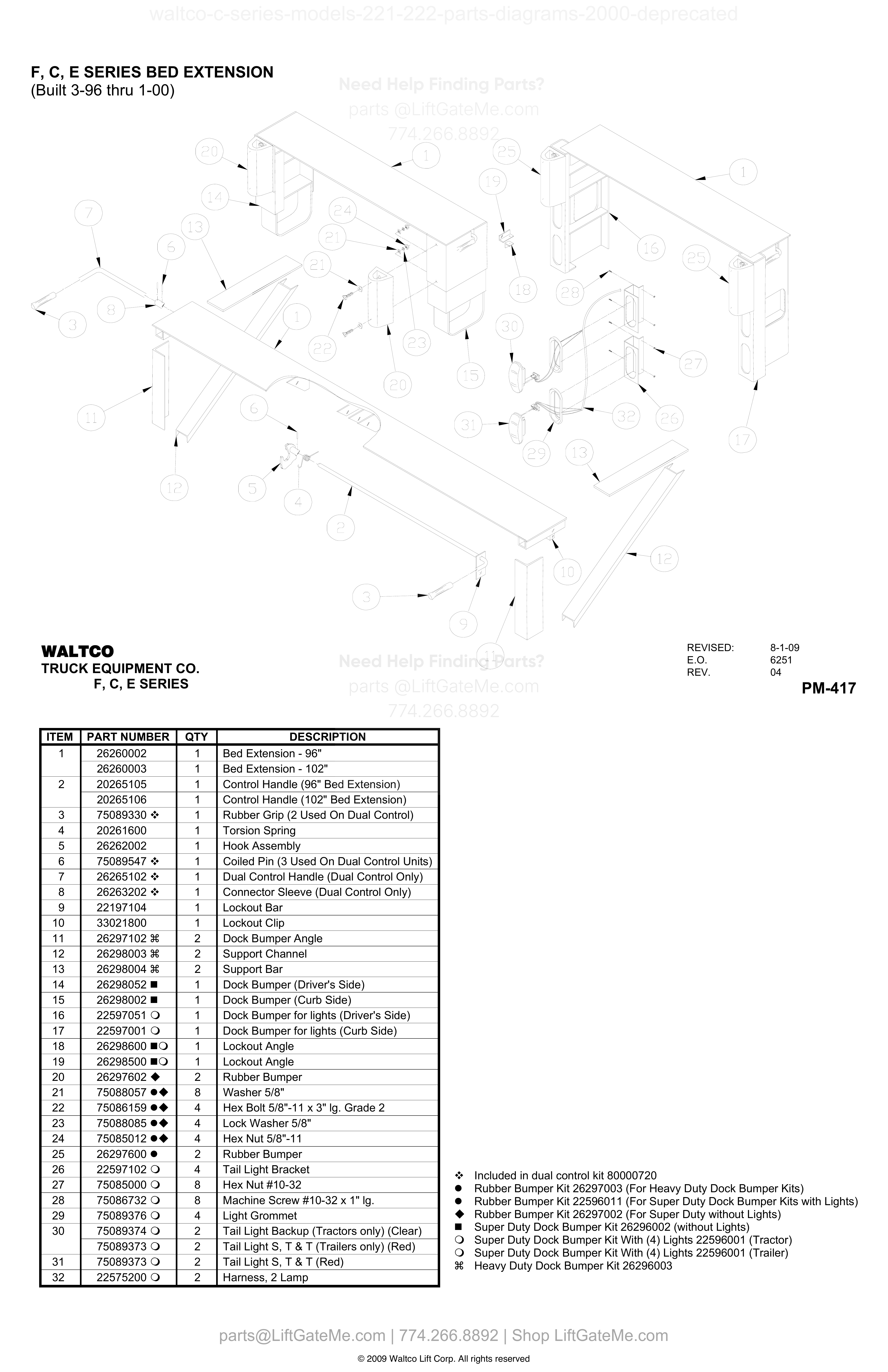
F, C, E SERIES BED EXTENSION (Built 3-96 thru 1-00)
| Item | Qty | Part Number | Description | Actions |
|---|---|---|---|---|
| 1 | 1 | 26260002 | Bed Extension - 96" | |
| 1 | 1 | 26260003 | Bed Extension - 102" | |
| 2 | 1 | 20265105 | Control Handle (96" Bed Extension) | |
| 2 | 1 | 20265106 | Control Handle (102" Bed Extension) | |
| 3 | 1 | 75089330 | Rubber Grip (2 Used On Dual Control) | |
| 4 | 1 | 20261600 | Torsion Spring | |
| 5 | 1 | 26262002 | Hook Assembly | |
| 6 | 1 | 75089547 | Coiled Pin (3 Used On Dual Control Units) | |
| 7 | 1 | 26265102 | Dual Control Handle (Dual Control Only) | |
| 8 | 1 | 26263202 | Connector Sleeve (Dual Control Only) | |
| 9 | 1 | 22197104 | Lockout Bar | |
| 10 | 1 | 33021800 | Lockout Clip | |
| 11 | 2 | 26297102 | Dock Bumper Angle | |
| 12 | 2 | 26298003 | Support Channel | |
| 13 | 2 | 26298004 | Support Bar | |
| 14 | 1 | 26298052 | Dock Bumper (Driver's Side) | |
| 15 | 1 | 26298002 | Dock Bumper (Curb Side) | |
| 16 | 1 | 22597051 | Dock Bumper for lights (Driver's Side) | |
| 17 | 1 | 22597001 | Dock Bumper for lights (Curb Side) | |
| 18 | 1 | 26298600 | Lockout Angle | |
| 19 | 1 | 26298500 | Lockout Angle | |
| 20 | 2 | 26297602 | Rubber Bumper | |
| 21 | 8 | 75088057 | Washer 5/8" | |
| 22 | 4 | 75086159 | Hex Bolt 5/8"-11 x 3" lg. Grade 2 | |
| 23 | 4 | 75088085 | Lock Washer 5/8" | |
| 24 | 4 | 75085012 | Hex Nut 5/8"-11 | |
| 25 | 2 | 26297600 | Rubber Bumper | |
| 26 | 4 | 22597102 | Tail Light Bracket | |
| 27 | 8 | 75085000 | Hex Nut #10-32 | |
| 28 | 8 | 75086732 | Machine Screw #10-32 x 1" lg. | |
| 29 | 4 | 75089376 | Light Grommet | |
| 30 | 2 | 75089374 | Tail Light Backup (Tractors only) (Clear) | |
| 30 | 2 | 75089373 | Tail Light S, T & T (Trailers only) (Red) | |
| 31 | 2 | 75089373 | Tail Light S, T & T (Red) | |
| 32 | 2 | 22575200 | Harness, 2 Lamp |
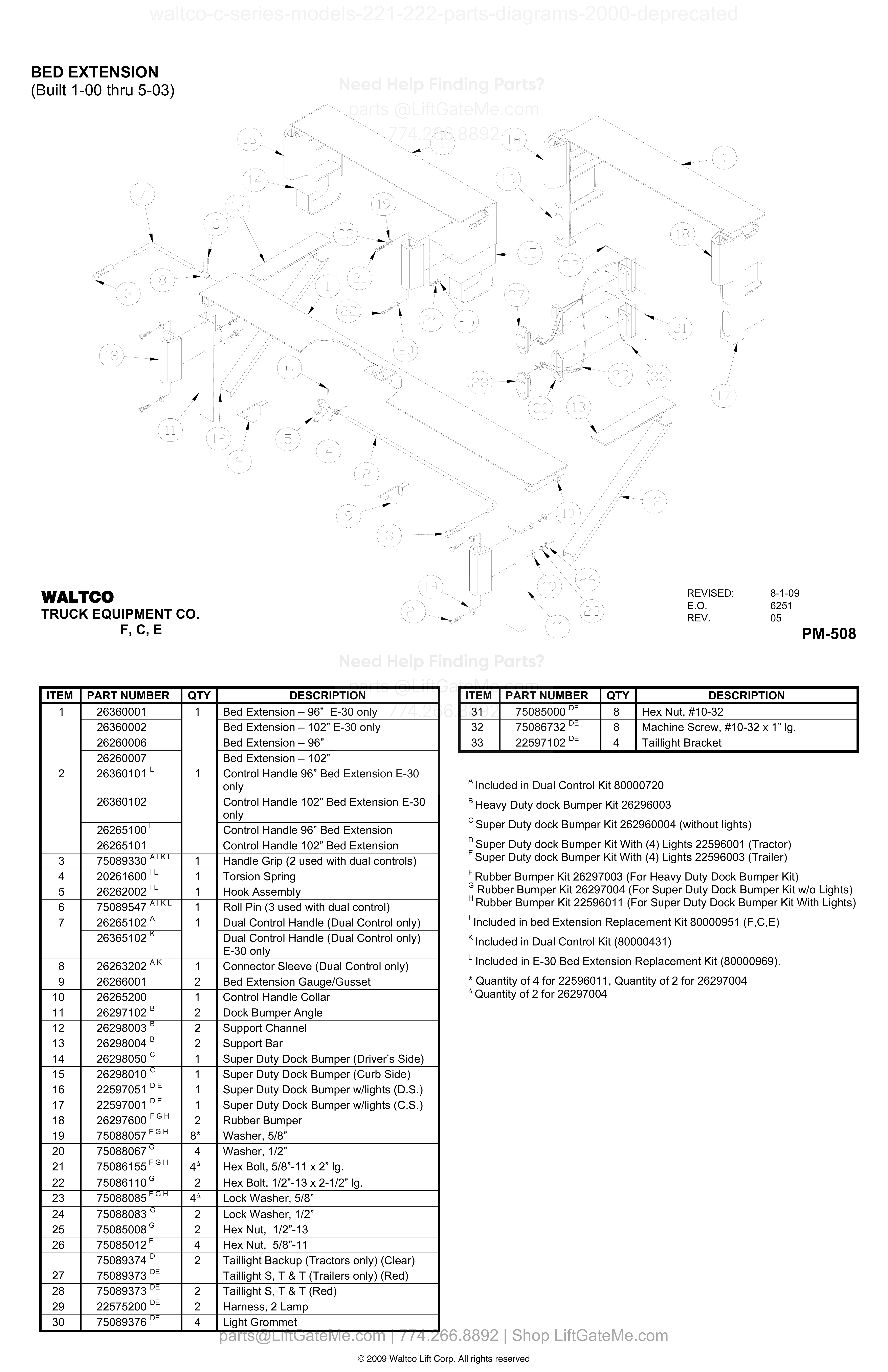
BED EXTENSION
| Item | Qty | Part Number | Description | Actions |
|---|---|---|---|---|
| 1 | 1 | 26360001 | Bed Extension – 96” E-30 only | |
| 1 | 1 | 26360002 | Bed Extension – 102” E-30 only | |
| 1 | 1 | 26260006 | Bed Extension – 96” | |
| 1 | 1 | 26260007 | Bed Extension – 102” | |
| 2 | 1 | 26360101 L | Control Handle 96” Bed Extension E-30 only | |
| 2 | 1 | 26360102 | Control Handle 102” Bed Extension E-30 only | |
| 2 | 1 | 26265100 I | Control Handle 96” Bed Extension | |
| 2 | 1 | 26265101 | Control Handle 102” Bed Extension | |
| 3 | 1 | 75089330^A,I,K,L | Handle Grip (2 used with dual controls) | |
| 4 | 1 | 20261600 I,L | Torsion Spring | |
| 5 | 1 | 26262002 I,L | Hook Assembly | |
| 6 | 1 | 75089547^A,I,K,L | Roll Pin (3 used with dual control) | |
| 7 | 1 | 26265102 A | Dual Control Handle (Dual Control only) | |
| 7 | 1 | 26365102 K | Dual Control Handle (Dual Control only) E-30 only | |
| 8 | 1 | 26263202 A,K | Connector Sleeve (Dual Control only) | |
| 9 | 2 | 26266001 | Bed Extension Gauge/Gusset | |
| 10 | 1 | 26265200 | Control Handle Collar | |
| 11 | 2 | 26297102 B | Dock Bumper Angle | |
| 12 | 2 | 26298003 B | Support Channel | |
| 13 | 2 | 26298004 B | Support Bar | |
| 14 | 1 | 26298050 C | Super Duty Dock Bumper (Driver’s Side) | |
| 15 | 1 | 26298010 C | Super Duty Dock Bumper (Curb Side) | |
| 16 | 1 | 22597051 D,E | Super Duty Dock Bumper w/lights (D.S.) | |
| 17 | 1 | 22597001 D,E | Super Duty Dock Bumper w/lights (C.S.) | |
| 18 | 2 | 26297600^F,G,H | Rubber Bumper | |
| 19 | 75088057^F,G,H | Washer, 5/8” | ||
| 20 | 4 | 75088067 G | Washer, 1/2” | |
| 21 | 75086155^F,G,H | Hex Bolt, 5/8”-11 x 2” lg. | ||
| 22 | 2 | 75086110 G | Hex Bolt, 1/2”-13 x 2-1/2” lg. | |
| 23 | 75088085^F,G,H | Lock Washer, 5/8” | ||
| 24 | 2 | 75088083 G | Lock Washer, 1/2” | |
| 25 | 2 | 75085008 G | Hex Nut, 1/2”-13 | |
| 26 | 4 | 75085012 F | Hex Nut, 5/8”-11 | |
| 27 | 2 | 75089374 D | Taillight Backup (Tractors only) (Clear) | |
| 27 | 2 | 75089373 D,E | Taillight S, T & T (Trailers only) (Red) | |
| 28 | 2 | 75089373 D,E | Taillight S, T & T (Red) | |
| 29 | 2 | 22575200 D,E | Harness, 2 Lamp | |
| 30 | 4 | 75089376 D,E | Light Grommet | |
| 31 | 8 | 75085000 | Hex Nut, #10-32 | |
| 32 | 8 | 75086732 D,E | Machine Screw, #10-32 x 1” lg. | |
| 33 | 4 | 22597102 D,E | Taillight Bracket |
Reference Notice
Manual links are provided for reference only. If you have any doubt, contact us — we’re happy to verify parts and help you purchase with confidence.
Have your liftgate serial number ready for faster assistance. Where to find it
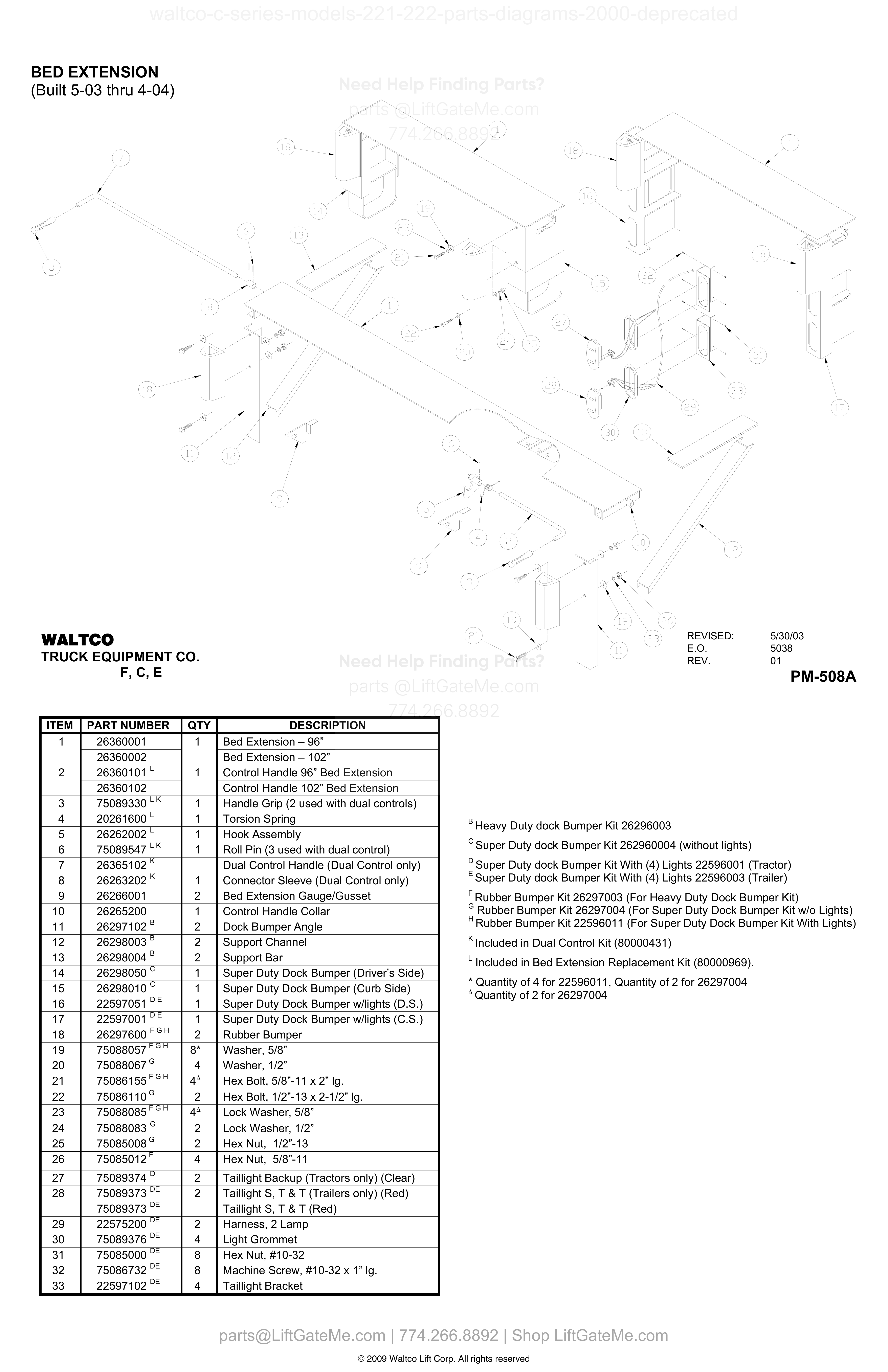
BED EXTENSION (Built 5-03 thru 4-04)
| Item | Qty | Part Number | Description | Actions |
|---|---|---|---|---|
| 1 | 1 | 26360001 | Bed Extension – 96” | |
| 1 | 26360002 | Bed Extension – 102” | ||
| 2 | 1 | 26360101 L | Control Handle 96” Bed Extension | |
| 2 | 26360102 | Control Handle 102” Bed Extension | ||
| 3 | 1 | 75089330 L,K | Handle Grip (2 used with dual controls) | |
| 4 | 1 | 20261600 L | Torsion Spring | |
| 5 | 1 | 26262002 L | Hook Assembly | |
| 6 | 1 | 75089547 L,K | Roll Pin (3 used with dual control) | |
| 7 | 1 | 26365102 K | Dual Control Handle (Dual Control only) | |
| 8 | 1 | 26263202 K | Connector Sleeve (Dual Control only) | |
| 9 | 2 | 26266001 | Bed Extension Gauge/Gusset | |
| 10 | 1 | 26265200 | Control Handle Collar | |
| 11 | 2 | 26297102 B | Dock Bumper Angle | |
| 12 | 2 | 26298003 B | Support Channel | |
| 13 | 2 | 26298004 B | Support Bar | |
| 14 | 1 | 26298050 C | Super Duty Dock Bumper (Driver’s Side) | |
| 15 | 1 | 26298010 C | Super Duty Dock Bumper (Curb Side) | |
| 16 | 1 | 22597051 D,E | Super Duty Dock Bumper w/lights (D.S.) | |
| 17 | 1 | 22597001 D,E | Super Duty Dock Bumper w/lights (C.S.) | |
| 18 | 2 | 26297600^F,G,H | Rubber Bumper | |
| 19 | 75088057^F,G,H | Washer, 5/8” | ||
| 20 | 75088067 G | Washer, 1/2” | ||
| 21 | 4^∆ | 75086155^F,G,H | Hex Bolt, 5/8”-11 x 2” lg. | |
| 22 | 2 | 75086110 G | Hex Bolt, 1/2”-13 x 2-1/2” lg. | |
| 23 | 4^∆ | 75088085^F,G,H | Lock Washer, 5/8” | |
| 24 | 2 | 75088083 G | Lock Washer, 1/2” | |
| 25 | 2 | 75085008 G | Hex Nut, 1/2”-13 | |
| 26 | 4 | 75085012 F | Hex Nut, 5/8”-11 | |
| 27 | 2 | 75089374 | Taillight Backup (Tractors only) (Clear) | |
| 28 | 2 | 75089373 D,E | Taillight S, T & T (Trailers only) (Red) | |
| 28 | 75089373 D,E | Taillight S, T & T (Red) | ||
| 29 | 2 | 22575200 D,E | Harness, 2 Lamp | |
| 30 | 4 | 75089376 D,E | Light Grommet | |
| 31 | 8 | 75085000 D,E | Hex Nut, #10-32 | |
| 32 | 8 | 75086732 D,E | Machine Screw, #10-32 x 1” lg. | |
| 33 | 4 | 22597102 D,E | Taillight Bracket |
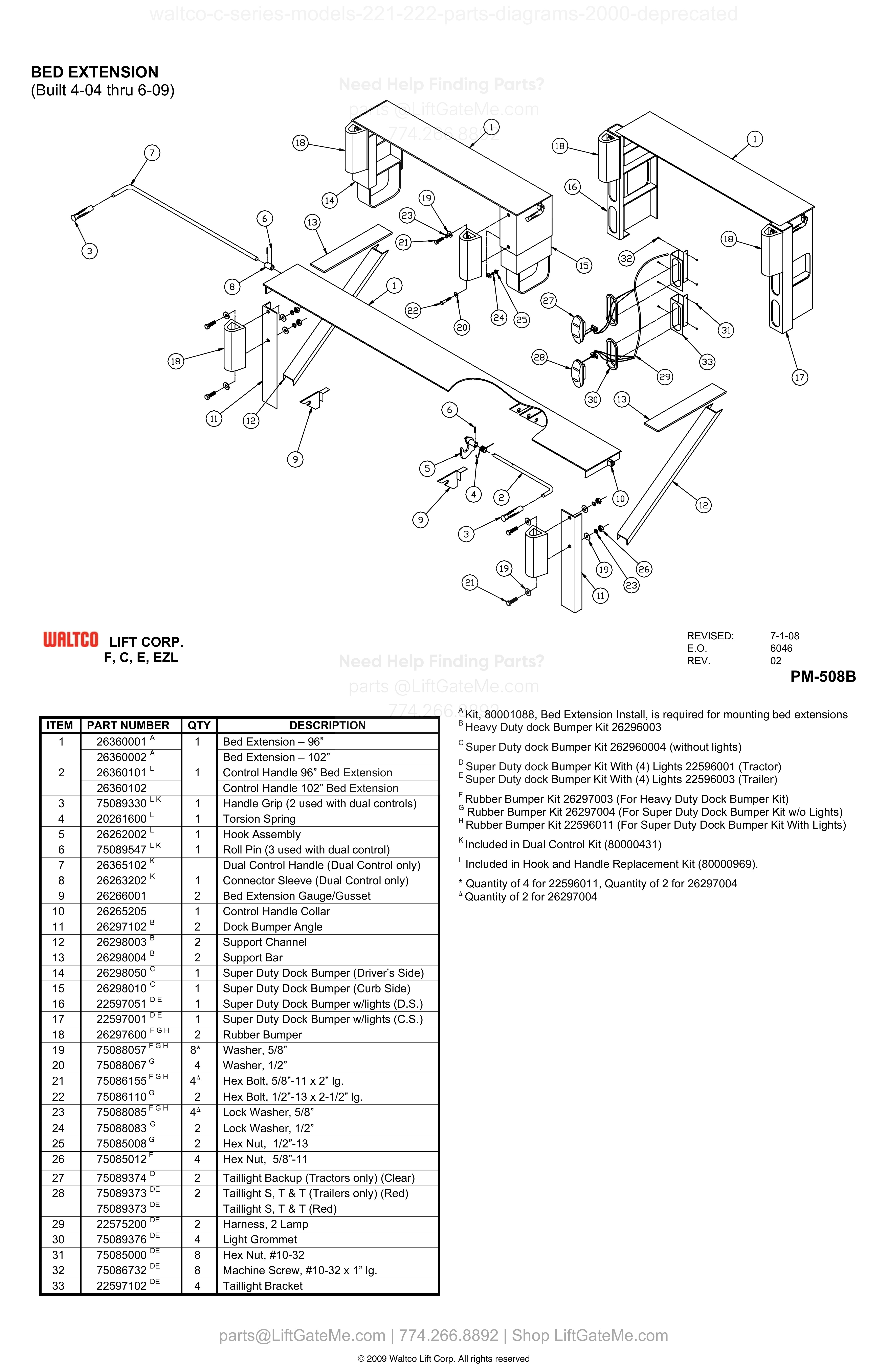
BED EXTENSION (Built 4-04 thru 6-09)
| Item | Qty | Part Number | Description | Actions |
|---|---|---|---|---|
| 1 | 1 | 26360001 A | Bed Extension – 96” | |
| 1 | 26360002 A | Bed Extension – 102” | ||
| 2 | 1 | 26360101 L | Control Handle 96” Bed Extension | |
| 2 | 26360102 | Control Handle 102” Bed Extension | ||
| 3 | 1 | 75089330 L,K | Handle Grip (2 used with dual controls) | |
| 4 | 1 | 20261600 L | Torsion Spring | |
| 5 | 1 | 26262002 L | Hook Assembly | |
| 6 | 1 | 75089547 L,K | Roll Pin (3 used with dual control) | |
| 7 | 26365102 K | Dual Control Handle (Dual Control only) | ||
| 8 | 1 | 26263202 K | Connector Sleeve (Dual Control only) | |
| 9 | 2 | 26266001 | Bed Extension Gauge/Gusset | |
| 10 | 1 | 26265205 | Control Handle Collar | |
| 11 | 2 | 26297102 B | Dock Bumper Angle | |
| 12 | 2 | 26298003 B | Support Channel | |
| 13 | 2 | 26298004 B | Support Bar | |
| 14 | 1 | 26298050 C | Super Duty Dock Bumper (Driver’s Side) | |
| 15 | 1 | 26298010 C | Super Duty Dock Bumper (Curb Side) | |
| 16 | 1 | 22597051 D,E | Super Duty Dock Bumper w/lights (D.S.) | |
| 17 | 1 | 22597001 D,E | Super Duty Dock Bumper w/lights (C.S.) | |
| 18 | 2 | 26297600^F,G,H | Rubber Bumper | |
| 19 | 75088057^F,G,H | Washer, 5/8” | ||
| 20 | 75088067 G | Washer, 1/2” | ||
| 21 | 75086155^F,G,H | Hex Bolt, 5/8”-11 x 2” lg. | ||
| 22 | 2 | 75086110 G | Hex Bolt, 1/2”-13 x 2-1/2” lg. | |
| 23 | 75088085^F,G,H | Lock Washer, 5/8” | ||
| 24 | 2 | 75088083 G | Lock Washer, 1/2” | |
| 25 | 2 | 75085008 G | Hex Nut, 1/2”-13 | |
| 26 | 4 | 75085012 F | Hex Nut, 5/8”-11 | |
| 27 | 2 | 75089374 D | Taillight Backup (Tractors only) (Clear) | |
| 28 | 2 | 75089373 D,E | Taillight S, T & T (Trailers only) (Red) | |
| 28 | 75089373 D,E | Taillight S, T & T (Red) | ||
| 29 | 2 | 22575200 D,E | Harness, 2 Lamp | |
| 30 | 4 | 75089376 D,E | Light Grommet | |
| 31 | 8 | 75085000 D,E | Hex Nut, #10-32 | |
| 32 | 8 | 75086732 D,E | Machine Screw, #10-32 x 1” lg. | |
| 33 | 4 | 22597102 D,E | Taillight Bracket |
Reference Notice
Manual links are provided for reference only. If you have any doubt, contact us — we’re happy to verify parts and help you purchase with confidence.
Have your liftgate serial number ready for faster assistance. Where to find it
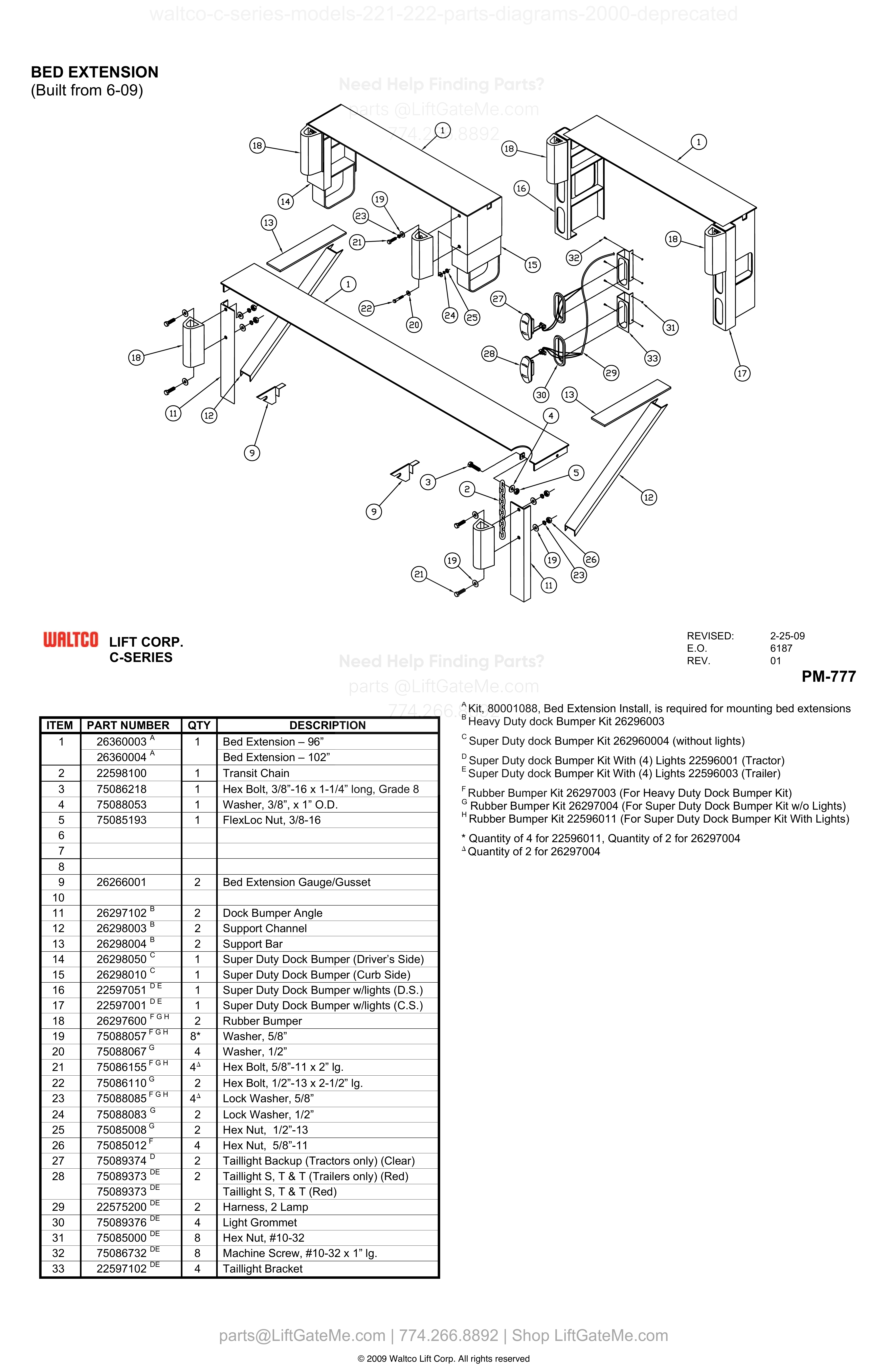
BED EXTENSION (Built from 6-09)
| Item | Qty | Part Number | Description | Actions |
|---|---|---|---|---|
| 1 | 1 | 26360003 A | Bed Extension – 96” | |
| 1 | 26360004 A | Bed Extension – 102” | ||
| 2 | 1 | 22598100 | Transit Chain | |
| 3 | 1 | 75086218 | Hex Bolt, 3/8”-16 x 1-1/4” long, Grade 8 | |
| 4 | 1 | 75088053 | Washer, 3/8”, x 1” O.D. | |
| 5 | 1 | 75085193 | FlexLoc Nut, 3/8-16 | |
| 9 | 2 | 26266001 | Bed Extension Gauge/Gusset | |
| 11 | 2 | 26297102 B | Dock Bumper Angle | |
| 12 | 2 | 26298003 B | Support Channel | |
| 13 | 2 | 26298004 B | Support Bar | |
| 14 | 1 | 26298050 C | Super Duty Dock Bumper (Driver’s Side) | |
| 15 | 1 | 26298010 C | Super Duty Dock Bumper (Curb Side) | |
| 16 | 1 | 22597051 D,E | Super Duty Dock Bumper w/lights (D.S.) | |
| 17 | 1 | 22597001 D,E | Super Duty Dock Bumper w/lights (C.S.) | |
| 18 | 2 | 26297600^F,G,H | Rubber Bumper | |
| 19 | 8* | 75088057^F,G,H | Washer, 5/8” | |
| 20 | 4 | 75088067 G | Washer, 1/2” | |
| 21 | 75086155^F,G,H | Hex Bolt, 5/8”-11 x 2” lg. | ||
| 22 | 2 | 75086110 G | Hex Bolt, 1/2”-13 x 2-1/2” lg. | |
| 23 | 75088085^F,G,H | Lock Washer, 5/8” | ||
| 24 | 2 | 75088083 G | Lock Washer, 1/2” | |
| 25 | 2 | 75085008 G | Hex Nut, 1/2”-13 | |
| 26 | 4 | 75085012 F | Hex Nut, 5/8”-11 | |
| 27 | 2 | 75089374 D | Taillight Backup (Tractors only) (Clear) | |
| 28 | 2 | 75089373 D,E | Taillight S, T & T (Trailers only) (Red) | |
| 28 | 75089373 D,E | Taillight S, T & T (Red) | ||
| 29 | 2 | 22575200 D,E | Harness, 2 Lamp | |
| 30 | 4 | 75089376 D,E | Light Grommet | |
| 31 | 8 | 75085000 D,E | Hex Nut, #10-32 | |
| 32 | 8 | 75086732 D,E | Machine Screw, #10-32 x 1” lg. | |
| 33 | 4 | 22597102 D,E | Taillight Bracket | |
| 6 | ||||
| 7 | ||||
| 8 | ||||
| 10 |
i


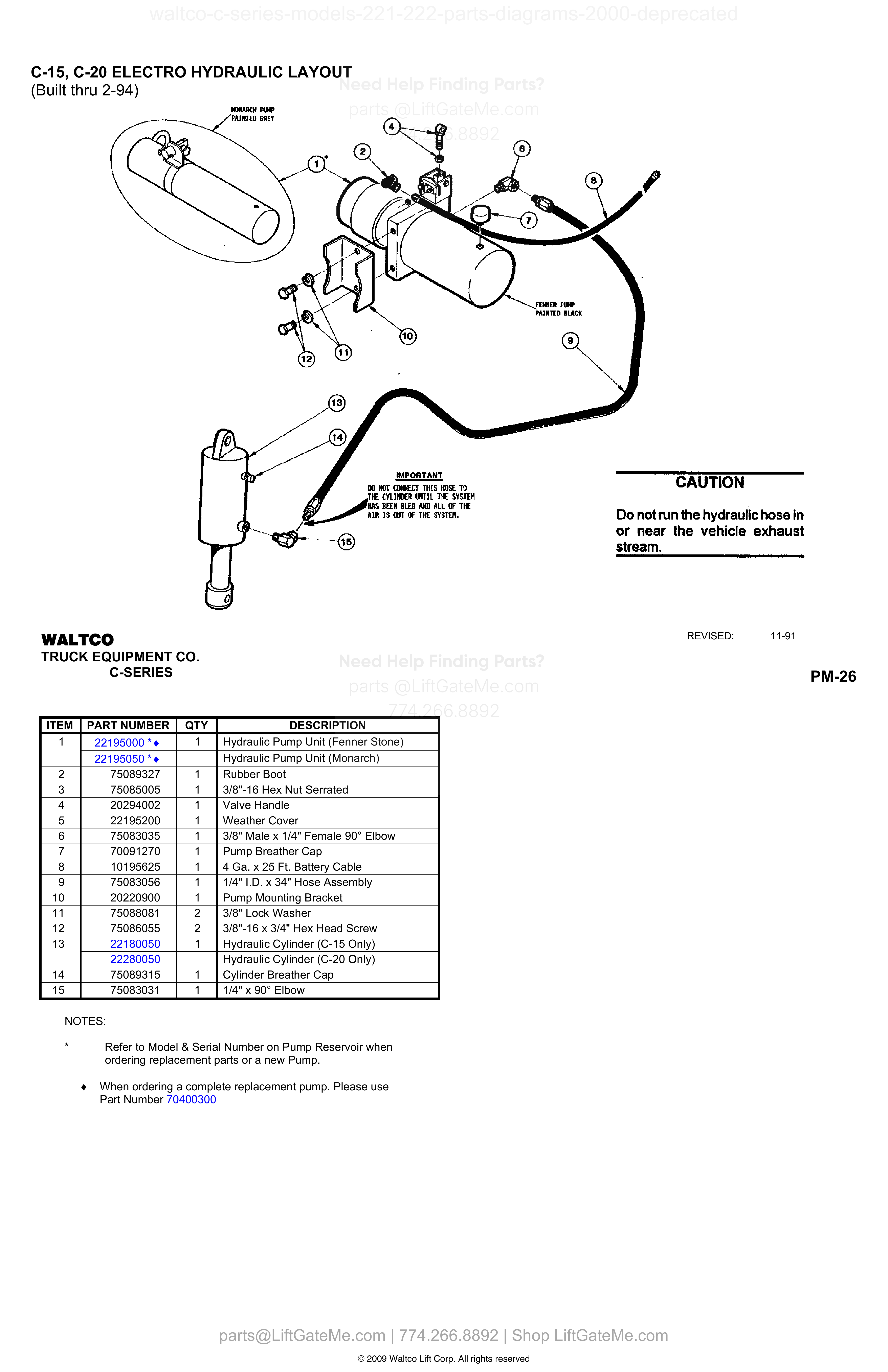
C-15, C-20 ELECTRO HYDRAULIC LAYOUT
| Item | Qty | Part Number | Description | Actions |
|---|---|---|---|---|
| 1 | 1 | 22195000 | Hydraulic Pump Unit (Fenner Stone) | |
| 1 | 22195050 | Hydraulic Pump Unit (Monarch) | ||
| 2 | 1 | 75089327 | Rubber Boot | |
| 3 | 1 | 75085005 | 3/8"-16 Hex Nut Serrated | |
| 4 | 1 | 20294002 | Valve Handle | |
| 5 | 1 | 22195200 | Weather Cover | |
| 6 | 1 | 75083035 | 3/8" Male x 1/4" Female 90° Elbow | |
| 7 | 1 | 70091270 | Pump Breather Cap | |
| 8 | 1 | 10195625 | 4 Ga. x 25 Ft. Battery Cable | |
| 9 | 1 | 75083056 | 1/4" I.D. x 34" Hose Assembly | |
| 10 | 1 | 20220900 | Pump Mounting Bracket | |
| 11 | 2 | 75088081 | 3/8" Lock Washer | |
| 12 | 2 | 75086055 | 3/8"-16 x 3/4" Hex Head Screw | |
| 13 | 1 | 22180050 | Hydraulic Cylinder (C-15 Only) | |
| 13 | 22280050 | Hydraulic Cylinder (C-20 Only) | ||
| 14 | 1 | 75089315 | Cylinder Breather Cap | |
| 15 | 1 | 75083031 | 1/4" x 90° Elbow |
Reference Notice
Manual links are provided for reference only. If you have any doubt, contact us — we’re happy to verify parts and help you purchase with confidence.
Have your liftgate serial number ready for faster assistance. Where to find it
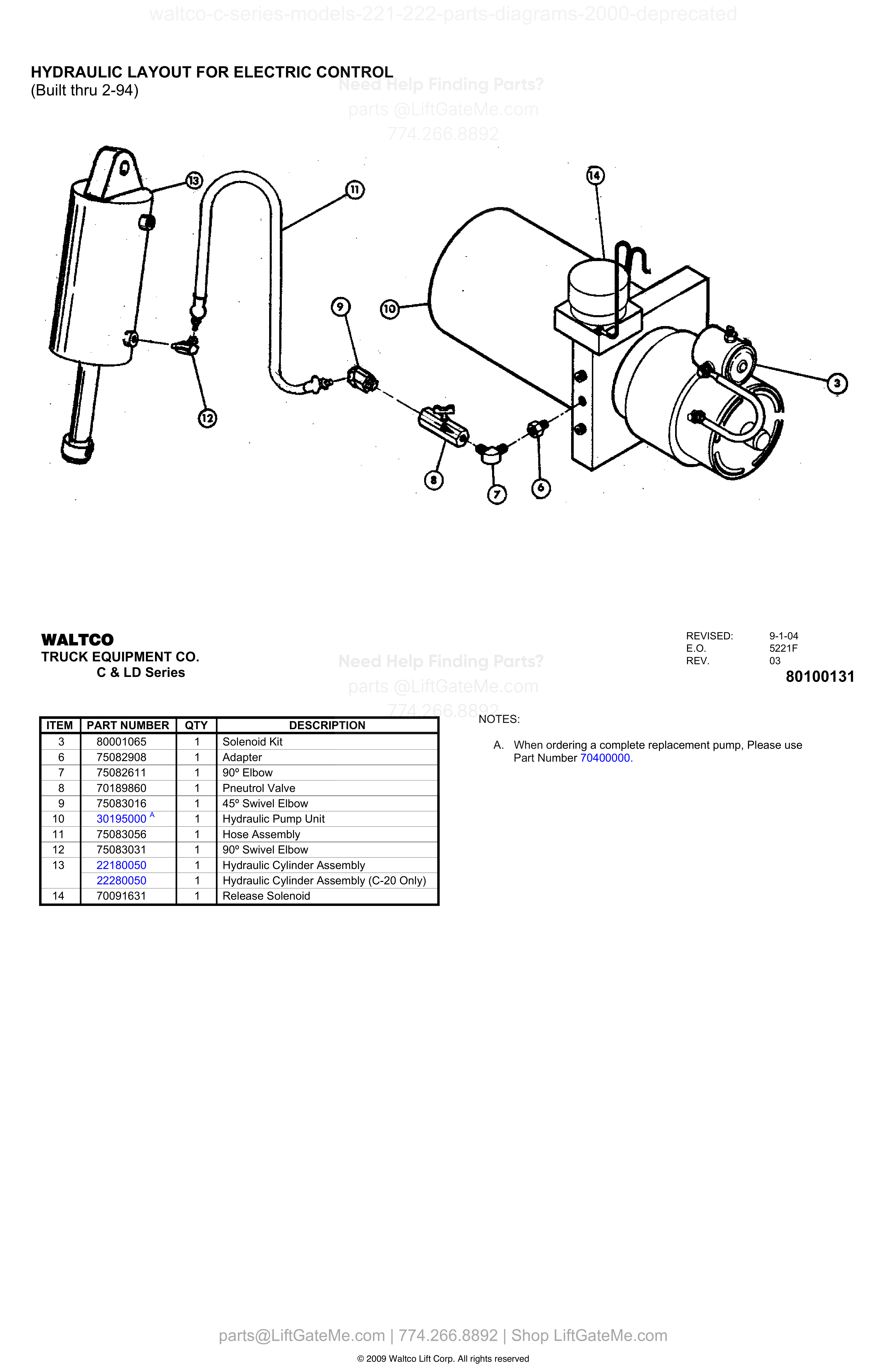
HYDRAULIC LAYOUT FOR ELECTRIC CONTROL
| Item | Qty | Part Number | Description | Actions |
|---|---|---|---|---|
| 3 | 1 | 80001065 | Solenoid Kit | |
| 6 | 1 | 75082908 | Adapter | |
| 7 | 1 | 75082611 | 90° Elbow | |
| 8 | 1 | 70189860 | Pneutrol Valve | |
| 9 | 1 | 75083016 A | 45° Swivel Elbow | |
| 10 | 1 | 30195000 A | Hydraulic Pump Unit | |
| 11 | 1 | 75083056 | Hose Assembly | |
| 12 | 1 | 75083031 | 90° Swivel Elbow | |
| 13 | 1 | 22180050 | Hydraulic Cylinder Assembly | |
| 13 | 1 | 22280050 | Hydraulic Cylinder Assembly (C-20 Only) | |
| 14 | 1 | 70091631 | Release Solenoid |
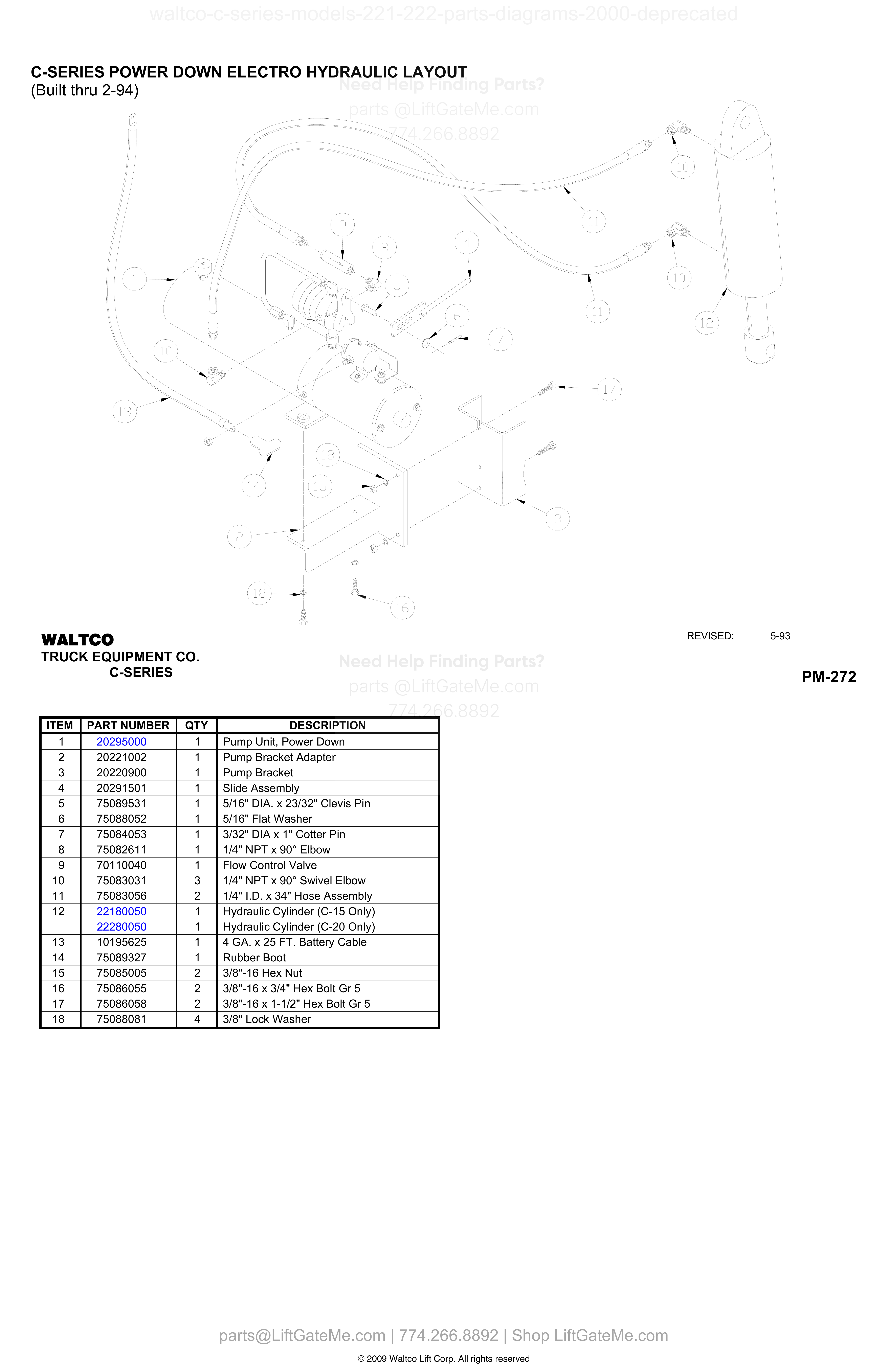
C-SERIES POWER DOWN ELECTRO HYDRAULIC LAYOUT (Built thru 2-94)
| Item | Qty | Part Number | Description | Actions |
|---|---|---|---|---|
| 1 | 1 | 20295000 | Pump Unit, Power Down | |
| 2 | 1 | 20221002 | Pump Bracket Adapter | |
| 3 | 1 | 20220900 | Pump Bracket | |
| 4 | 1 | 20291501 | Slide Assembly | |
| 5 | 1 | 75089531 | 5/16" DIA. x 23/32" Clevis Pin | |
| 6 | 1 | 75088052 | 5/16" Flat Washer | |
| 7 | 1 | 75084053 | 3/32" DIA x 1" Cotter Pin | |
| 8 | 1 | 75082611 | 1/4" NPT x 90° Elbow | |
| 9 | 1 | 70110040 | Flow Control Valve | |
| 10 | 3 | 75083031 | 1/4" NPT x 90° Swivel Elbow | |
| 11 | 2 | 75083056 | 1/4" I.D. x 34" Hose Assembly | |
| 12 | 1 | 22180050 | Hydraulic Cylinder (C-15 Only) | |
| 12 | 1 | 22280050 | Hydraulic Cylinder (C-20 Only) | |
| 13 | 1 | 10195625 | 4 GA. x 25 FT. Battery Cable | |
| 14 | 1 | 75089327 | Rubber Boot | |
| 15 | 2 | 75085005 | 3/8"-16 Hex Nut | |
| 16 | 2 | 75086055 | 3/8"-16 x 3/4" Hex Bolt Gr 5 | |
| 17 | 2 | 75086058 | 3/8"-16 x 1-1/2" Hex Bolt Gr 5 | |
| 18 | 4 | 75088081 | 3/8" Lock Washer |
Reference Notice
Manual links are provided for reference only. If you have any doubt, contact us — we’re happy to verify parts and help you purchase with confidence.
Have your liftgate serial number ready for faster assistance. Where to find it
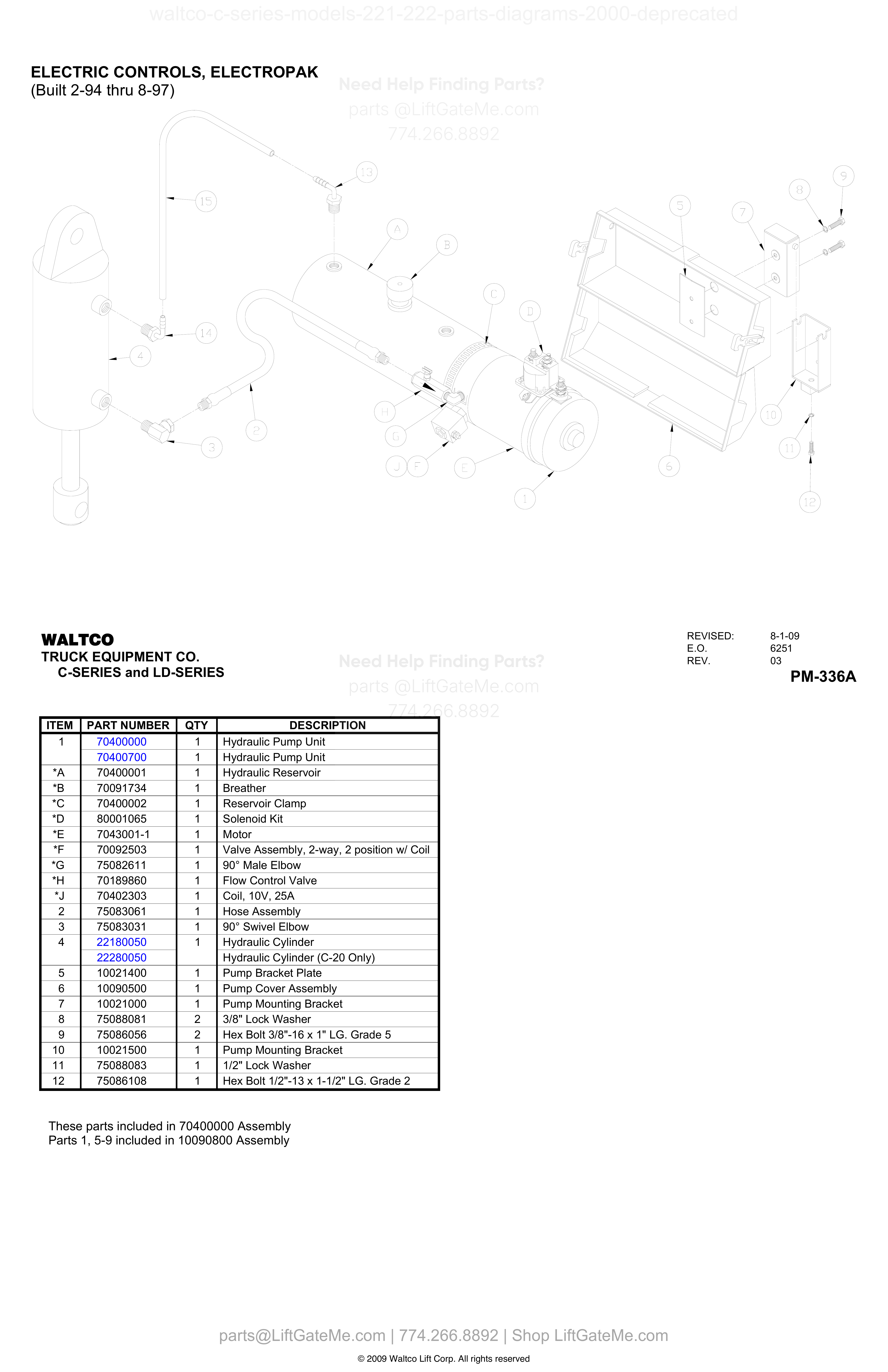
ELECTRIC CONTROLS, ELECTROPAK
| Item | Qty | Part Number | Description | Actions |
|---|---|---|---|---|
| 1 | 1 | 70400000 | Hydraulic Pump Unit | |
| 1 | 1 | 70400700 | Hydraulic Pump Unit | |
| *A | 1 | 70400001 | Hydraulic Reservoir | |
| *B | 1 | 70091734 | Breather | |
| *C | 1 | 70400002 | Reservoir Clamp | |
| *D | 1 | 80001065 | Solenoid Kit | |
| *E | 1 | 7043001-1 | Motor | |
| *F | 1 | 70092503 | Valve Assembly, 2-way, 2 position w/ Coil | |
| *G | 1 | 75082611 | 90° Male Elbow | |
| *H | 1 | 70189860 | Flow Control Valve | |
| *J | 1 | 70402303 | Coil, 10V, 25A | |
| 2 | 1 | 75083061 | Hose Assembly | |
| 3 | 1 | 75083031 | 90° Swivel Elbow | |
| 4 | 1 | 22180050 | Hydraulic Cylinder | |
| 4 | 22280050 | Hydraulic Cylinder (C-20 Only) | ||
| 5 | 1 | 10021400 | Pump Bracket Plate | |
| 6 | 1 | 10090500 | Pump Cover Assembly | |
| 7 | 1 | 10021000 | Pump Mounting Bracket | |
| 8 | 2 | 75088081 | 3/8" Lock Washer | |
| 9 | 2 | 75086056 | Hex Bolt 3/8"-16 x 1" LG. Grade 5 | |
| 10 | 1 | 10021500 | Pump Mounting Bracket | |
| 11 | 1 | 75088083 | 1/2" Lock Washer | |
| 12 | 1 | 75086108 | Hex Bolt 1/2"-13 x 1-1/2" LG. Grade 2 |
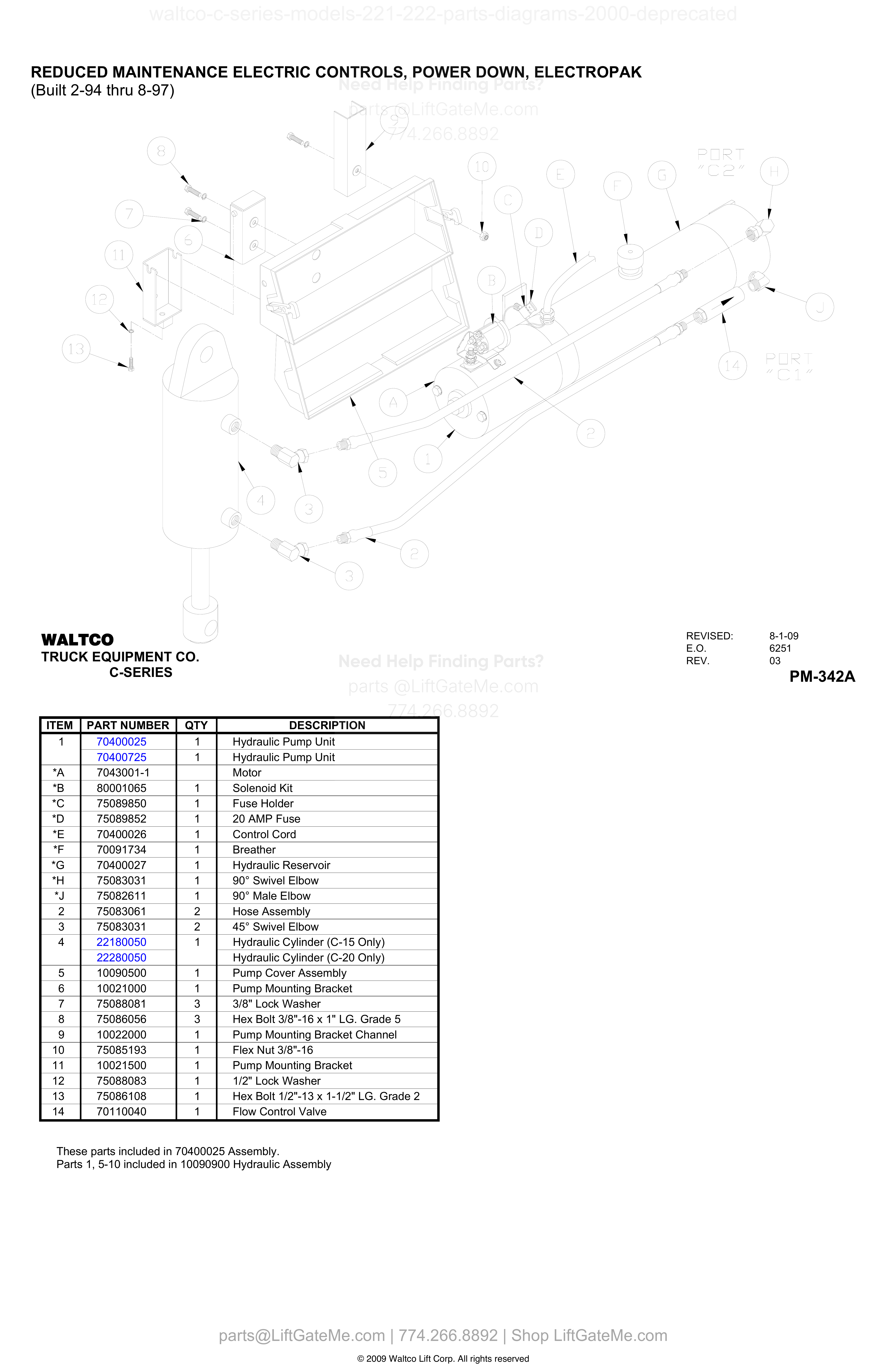
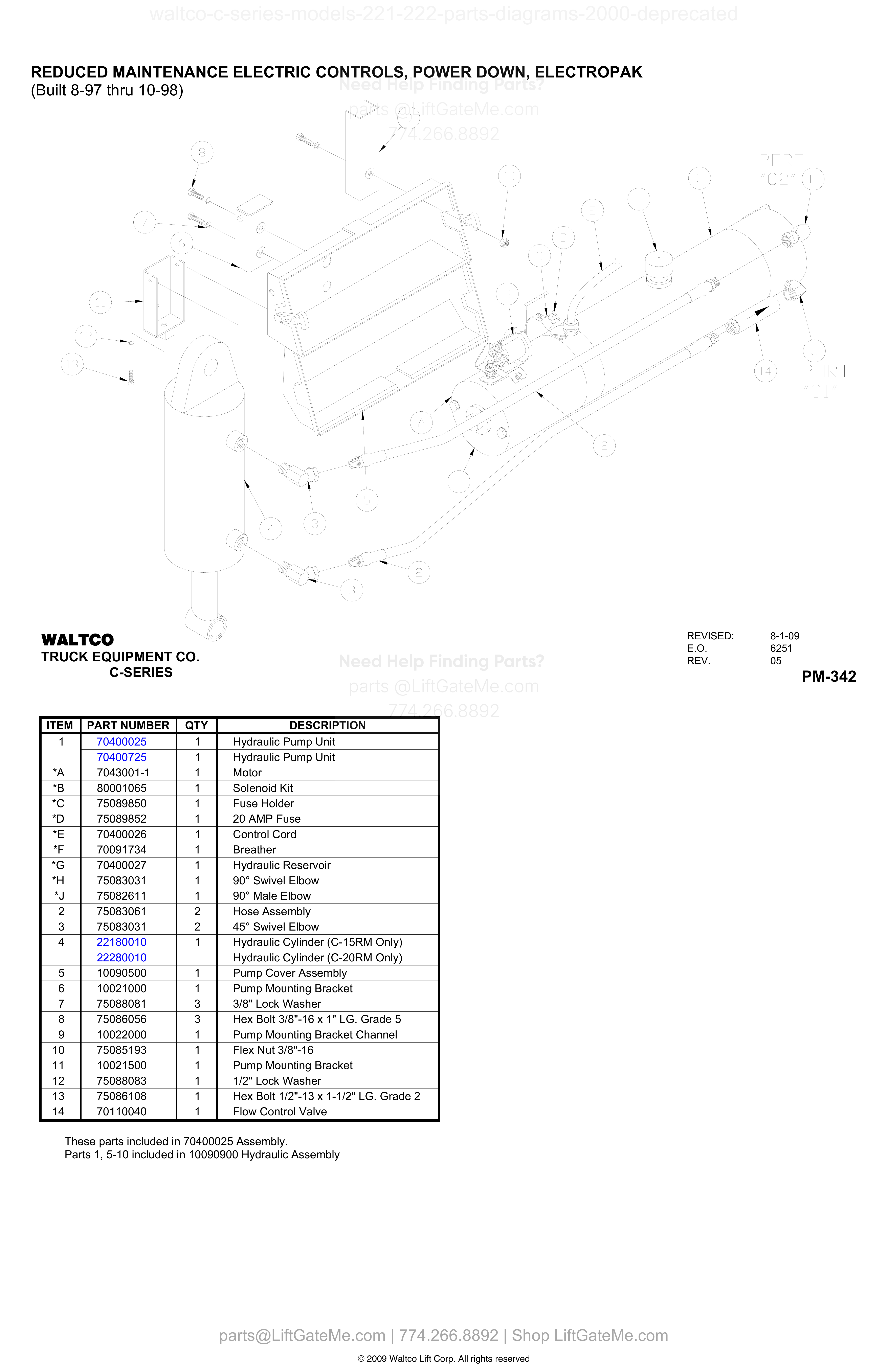
REDUCED MAINTENANCE ELECTRIC CONTROLS, POWER DOWN, ELECTROPAK (Built 2-94 thru 8-97)
| Item | Qty | Part Number | Description | Actions |
|---|---|---|---|---|
| 1 | 1 | 70400025 | Hydraulic Pump Unit | |
| 1 | 1 | 70400725 | Hydraulic Pump Unit | |
| *A | 7043001-1 | Motor | ||
| *B | 1 | 80001065 | Solenoid Kit | |
| *C | 1 | 75089850 | Fuse Holder | |
| *D | 1 | 75089852 | 20 AMP Fuse | |
| *E | 1 | 70400026 | Control Cord | |
| *F | 1 | 70091734 | Breather | |
| *G | 1 | 70400027 | Hydraulic Reservoir | |
| *H | 1 | 75083031 | 90° Swivel Elbow | |
| *J | 1 | 75082611 | 90° Male Elbow | |
| 2 | 2 | 75083061 | Hose Assembly | |
| 3 | 2 | 75083031 | 45° Swivel Elbow | |
| 4 | 1 | 22180050 | Hydraulic Cylinder (C-15 Only) | |
| 4 | 22280050 | Hydraulic Cylinder (C-20 Only) | ||
| 5 | 1 | 10090500 | Pump Cover Assembly | |
| 6 | 1 | 10021000 | Pump Mounting Bracket | |
| 7 | 3 | 75088081 | 3/8" Lock Washer | |
| 8 | 3 | 75086056 | Hex Bolt 3/8"-16 x 1" LG. Grade 5 | |
| 9 | 1 | 10022000 | Pump Mounting Bracket Channel | |
| 10 | 1 | 75085193 | Flex Nut 3/8"-16 | |
| 11 | 1 | 10021500 | Pump Mounting Bracket | |
| 12 | 1 | 75088083 | 1/2" Lock Washer | |
| 13 | 1 | 75086108 | Hex Bolt 1/2"-13 x 1-1/2" LG. Grade 2 | |
| 14 | 1 | 70110040 | Flow Control Valve |
Reference Notice
Manual links are provided for reference only. If you have any doubt, contact us — we’re happy to verify parts and help you purchase with confidence.
Have your liftgate serial number ready for faster assistance. Where to find it
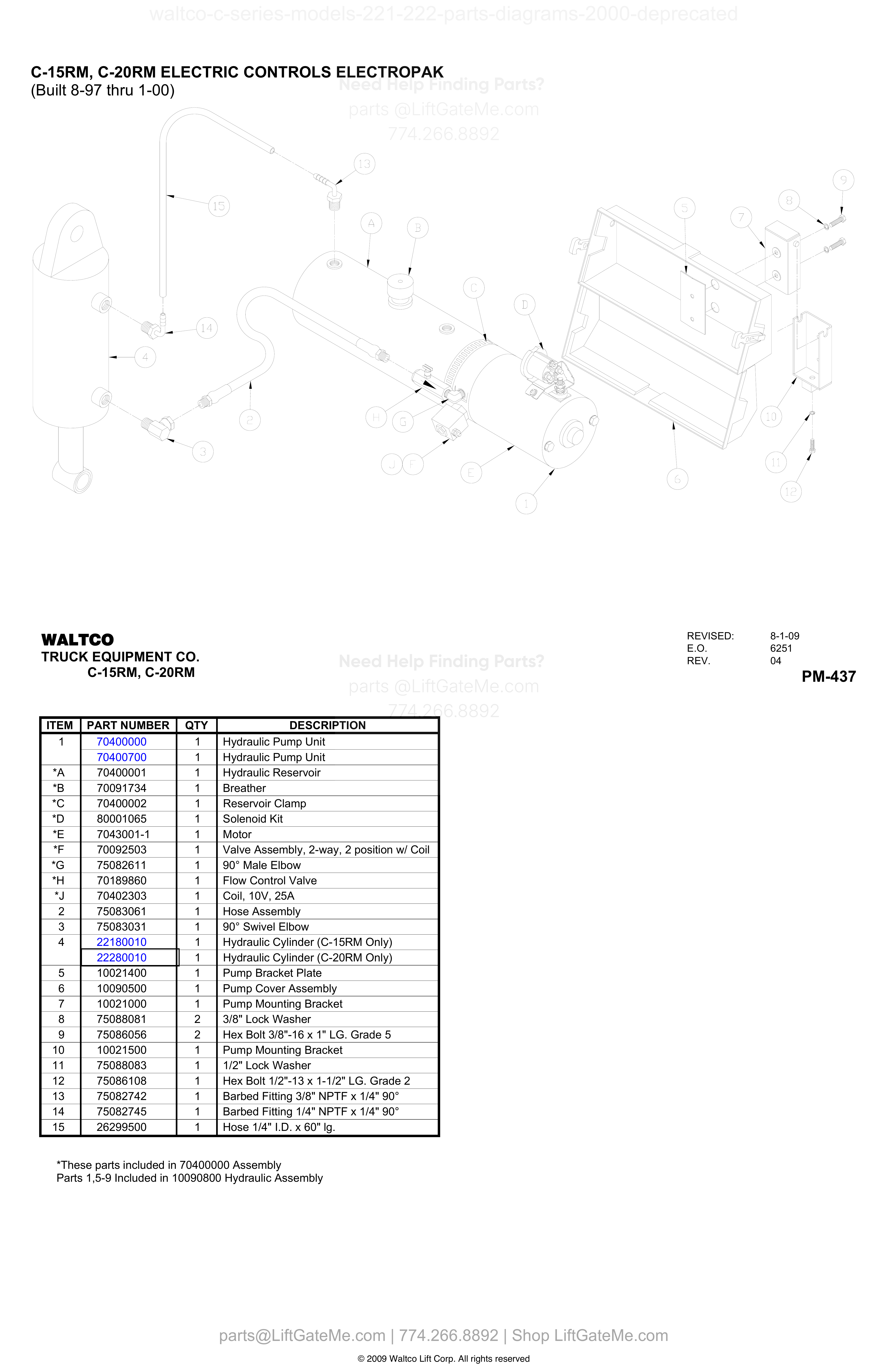
C-15RM, C-20RM ELECTRIC CONTROLS ELECTROPAK
| Item | Qty | Part Number | Description | Actions |
|---|---|---|---|---|
| 1 | 1 | 70400000 | Hydraulic Pump Unit | |
| 1 | 1 | 70400700 | Hydraulic Pump Unit | |
| *A | 1 | 70400001 | Hydraulic Reservoir | |
| *B | 1 | 70091734 | Breather | |
| *C | 1 | 70400002 | Reservoir Clamp | |
| *D | 1 | 80001065 | Solenoid Kit | |
| *E | 1 | 7043001-1 | Motor | |
| *F | 1 | 70092503 | Valve Assembly, 2-way, 2 position w/ Coil | |
| *G | 1 | 75082611 | 90° Male Elbow | |
| *H | 1 | 70189860 | Flow Control Valve | |
| *J | 1 | 70402303 | Coil, 10V, 25A | |
| 2 | 1 | 75083061 | Hose Assembly | |
| 3 | 1 | 75083031 | 90° Swivel Elbow | |
| 4 | 1 | 22180010 | Hydraulic Cylinder (C-15RM Only) | |
| 4 | 1 | 22280010 | Hydraulic Cylinder (C-20RM Only) | |
| 5 | 1 | 10021400 | Pump Bracket Plate | |
| 6 | 1 | 10090500 | Pump Cover Assembly | |
| 7 | 1 | 10021000 | Pump Mounting Bracket | |
| 8 | 2 | 75088081 | 3/8" Lock Washer | |
| 9 | 2 | 75086056 | Hex Bolt 3/8"-16 x 1" LG. Grade 5 | |
| 10 | 1 | 10021500 | Pump Mounting Bracket | |
| 11 | 1 | 75088083 | 1/2" Lock Washer | |
| 12 | 1 | 75086108 | Hex Bolt 1/2"-13 x 1-1/2" LG. Grade 2 | |
| 13 | 1 | 75082742 | Barbed Fitting 3/8" NPTF x 1/4" 90° | |
| 14 | 1 | 75082745 | Barbed Fitting 1/4" NPTF x 1/4" 90° | |
| 15 | 1 | 26299500 | Hose 1/4" I.D. x 60" lg. |
REDUCED MAINTENANCE ELECTRIC CONTROLS, POWER DOWN, ELECTROPAK
| Item | Qty | Part Number | Description | Actions |
|---|---|---|---|---|
| 1 | 1 | 70400025 | Hydraulic Pump Unit | |
| 1 | 1 | 70400725 | Hydraulic Pump Unit | |
| *A | 1 | 7043001-1 | Motor | |
| *B | 1 | 80001065 | Solenoid Kit | |
| *C | 1 | 75089850 | Fuse Holder | |
| *D | 1 | 75089852 | 20 AMP Fuse | |
| *E | 1 | 70400026 | Control Cord | |
| *F | 1 | 70091734 | Breather | |
| *G | 1 | 70400027 | Hydraulic Reservoir | |
| *H | 1 | 75083031 | 90° Swivel Elbow | |
| *J | 1 | 75082611 | 90° Male Elbow | |
| 2 | 2 | 75083061 | Hose Assembly | |
| 3 | 2 | 75083031 | 45° Swivel Elbow | |
| 4 | 1 | 22180010 | Hydraulic Cylinder (C-15RM Only) | |
| 4 | 22280010 | Hydraulic Cylinder (C-20RM Only) | ||
| 5 | 1 | 10090500 | Pump Cover Assembly | |
| 6 | 1 | 10021000 | Pump Mounting Bracket | |
| 7 | 3 | 75088081 | 3/8" Lock Washer | |
| 8 | 3 | 75086056 | Hex Bolt 3/8"-16 x 1" LG. Grade 5 | |
| 9 | 1 | 10022000 | Pump Mounting Bracket Channel | |
| 10 | 1 | 75085193 | Flex Nut 3/8"-16 | |
| 11 | 1 | 10021500 | Pump Mounting Bracket | |
| 12 | 1 | 75088083 | 1/2" Lock Washer | |
| 13 | 1 | 75086108 | Hex Bolt 1/2"-13 x 1-1/2" LG. Grade 2 | |
| 14 | 1 | 70110040 | Flow Control Valve |
Reference Notice
Manual links are provided for reference only. If you have any doubt, contact us — we’re happy to verify parts and help you purchase with confidence.
Have your liftgate serial number ready for faster assistance. Where to find it
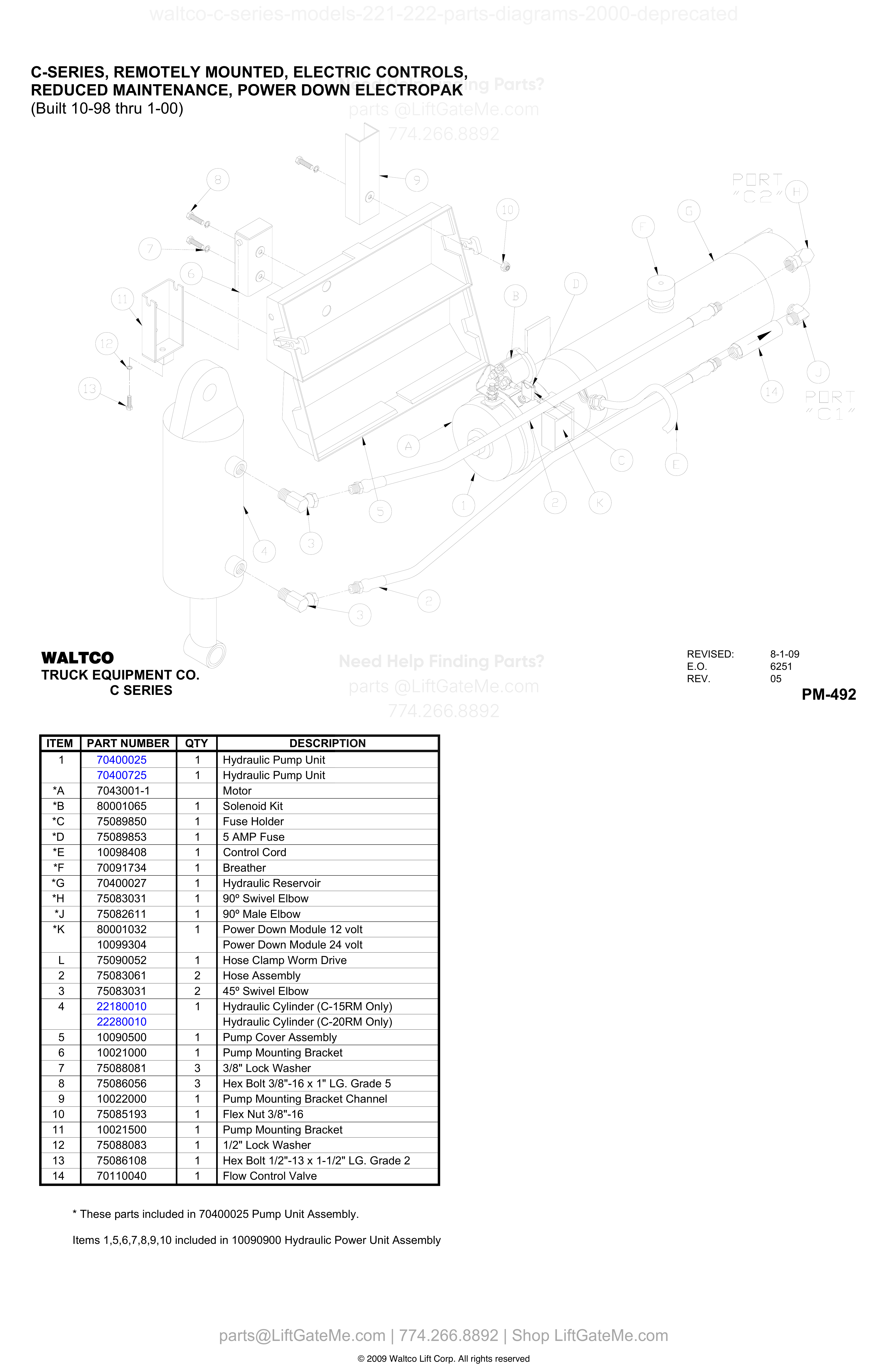
C-SERIES, REMOTELY MOUNTED, ELECTRIC CONTROLS, REDUCED MAINTENANCE, POWER DOWN ELECTROPAK (Built 10-98 thru 1-00)
| Item | Qty | Part Number | Description | Actions |
|---|---|---|---|---|
| 1 | 1 | 70400025 | Hydraulic Pump Unit | |
| 1 | 1 | 70400725 | Hydraulic Pump Unit | |
| *A | 7043001-1 | Motor | ||
| *B | 1 | 80001065 | Solenoid Kit | |
| *C | 1 | 75089850 | Fuse Holder | |
| *D | 1 | 75089853 | 5 AMP Fuse | |
| *E | 1 | 10098408 | Control Cord | |
| *F | 1 | 70091734 | Breather | |
| *G | 1 | 70400027 | Hydraulic Reservoir | |
| *H | 1 | 75083031 | 90° Swivel Elbow | |
| *J | 1 | 75082611 | 90° Male Elbow | |
| *K | 1 | 80001032 | Power Down Module 12 volt | |
| *K | 10099304 | Power Down Module 24 volt | ||
| L | 1 | 75090052 | Hose Clamp Worm Drive | |
| 2 | 2 | 75083061 | Hose Assembly | |
| 3 | 2 | 75083031 | 45° Swivel Elbow | |
| 4 | 1 | 22180010 | Hydraulic Cylinder (C-15RM Only) | |
| 4 | 22280010 | Hydraulic Cylinder (C-20RM Only) | ||
| 5 | 1 | 10090500 | Pump Cover Assembly | |
| 6 | 1 | 10021000 | Pump Mounting Bracket | |
| 7 | 3 | 75088081 | 3/8" Lock Washer | |
| 8 | 3 | 75086056 | Hex Bolt 3/8"-16 x 1" LG. Grade 5 | |
| 9 | 1 | 10022000 | Pump Mounting Bracket Channel | |
| 10 | 1 | 75085193 | Flex Nut 3/8"-16 | |
| 11 | 1 | 10021500 | Pump Mounting Bracket | |
| 12 | 1 | 75088083 | 1/2" Lock Washer | |
| 13 | 1 | 75086108 | Hex Bolt 1/2"-13 x 1-1/2" LG. Grade 2 | |
| 14 | 1 | 70110040 | Flow Control Valve |
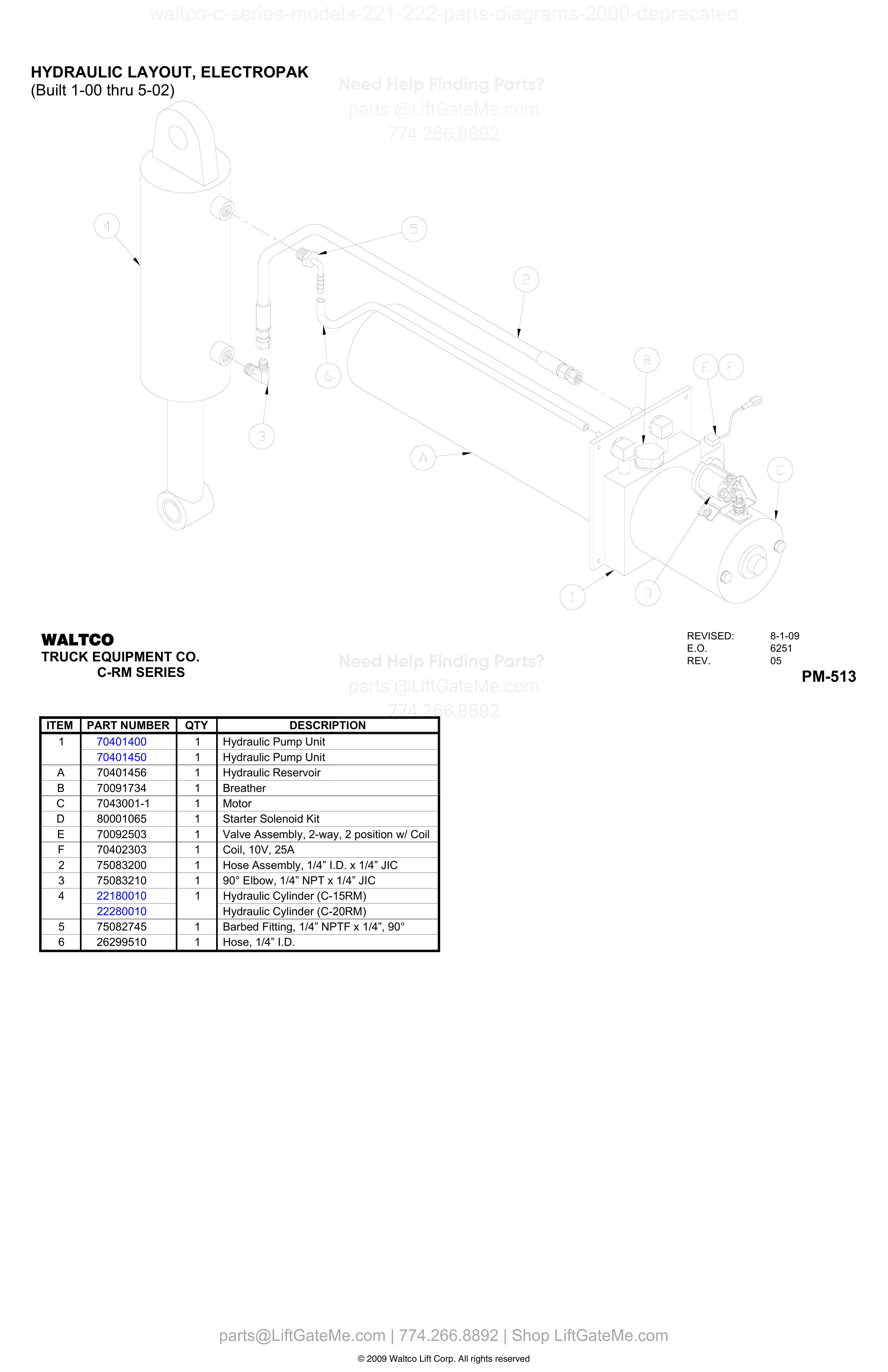
HYDRAULIC LAYOUT, ELECTROPAK
| Item | Qty | Part Number | Description | Actions |
|---|---|---|---|---|
| 1 | 1 | 70401400 | Hydraulic Pump Unit | |
| 1 | 1 | 70401450 | Hydraulic Pump Unit | |
| A | 1 | 70401456 | Hydraulic Reservoir | |
| B | 1 | 70091734 | Breather | |
| C | 1 | 7043001-1 | Motor | |
| D | 1 | 80001065 | Starter Solenoid Kit | |
| E | 1 | 70092503 | Valve Assembly, 2-way, 2 position w/ Coil | |
| F | 1 | 70402303 | Coil, 10V, 25A | |
| 2 | 1 | 75083200 | Hose Assembly, 1/4” I.D. x 1/4” JIC | |
| 3 | 1 | 75083210 | 90° Elbow, 1/4” NPT x 1/4” JIC | |
| 4 | 1 | 22180010 | Hydraulic Cylinder (C-15RM) | |
| 4 | 22280010 | Hydraulic Cylinder (C-20RM) | ||
| 5 | 1 | 75082745 | Barbed Fitting, 1/4” NPTF x 1/4”, 90° | |
| 6 | 1 | 26299510 | Hose, 1/4” I.D. |
Reference Notice
Manual links are provided for reference only. If you have any doubt, contact us — we’re happy to verify parts and help you purchase with confidence.
Have your liftgate serial number ready for faster assistance. Where to find it
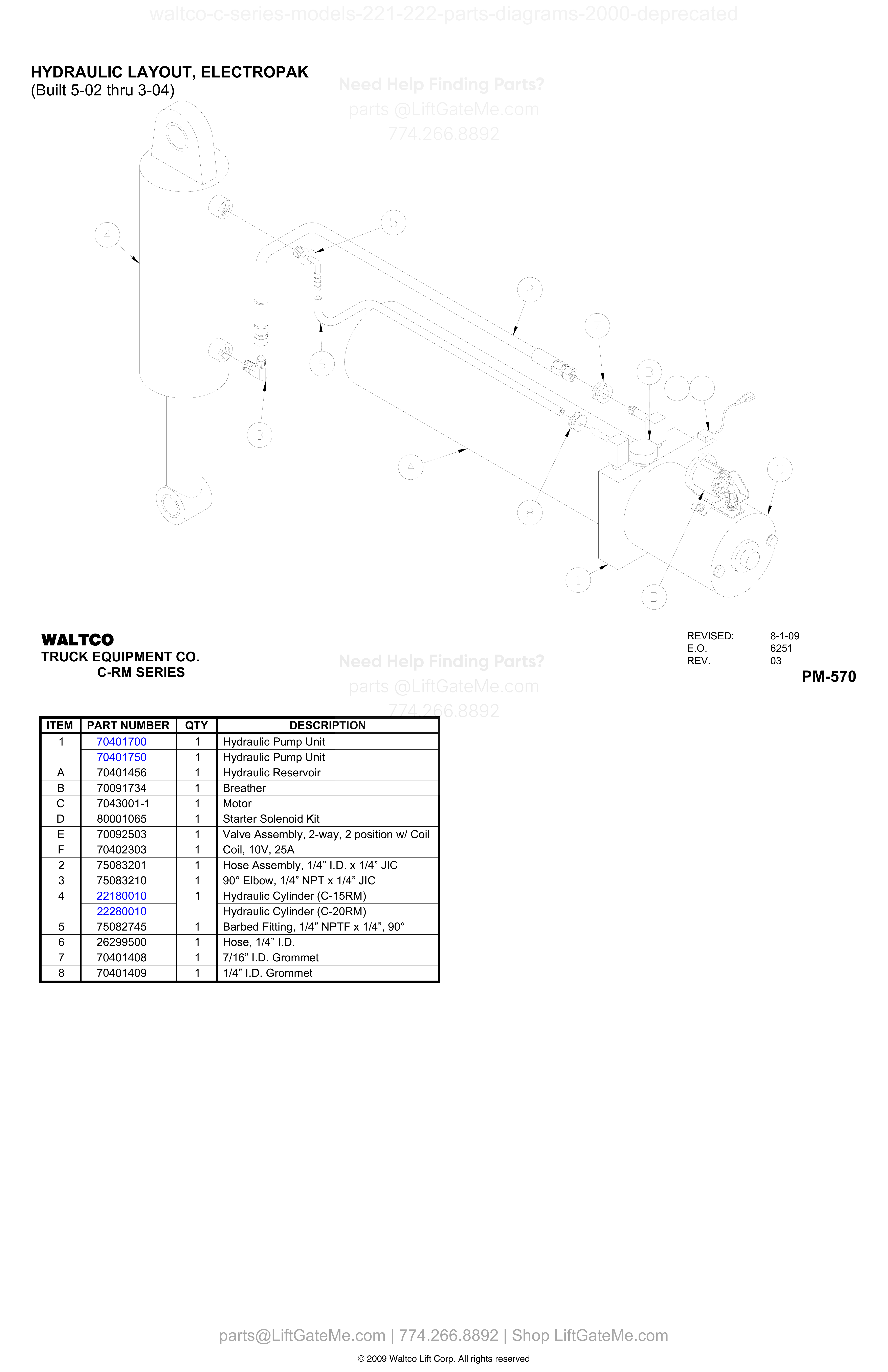
HYDRAULIC LAYOUT, ELECTROPAK (Built 5-02 thru 3-04)
| Item | Qty | Part Number | Description | Actions |
|---|---|---|---|---|
| 1 | 1 | 70401700 | Hydraulic Pump Unit | |
| 1 | 1 | 70401750 | Hydraulic Pump Unit | |
| A | 1 | 70401456 | Hydraulic Reservoir | |
| B | 1 | 70091734 | Breather | |
| C | 1 | 7043001-1 | Motor | |
| D | 1 | 80001065 | Starter Solenoid Kit | |
| E | 1 | 70092503 | Valve Assembly, 2-way, 2 position w/ Coil | |
| F | 1 | 70402303 | Coil, 10V, 25A | |
| 2 | 1 | 75083201 | Hose Assembly, 1/4” I.D. x 1/4” JIC | |
| 3 | 1 | 75083210 | 90° Elbow, 1/4” NPT x 1/4” JIC | |
| 4 | 1 | 22180010 | Hydraulic Cylinder (C-15RM) | |
| 4 | 22280010 | Hydraulic Cylinder (C-20RM) | ||
| 5 | 1 | 75082745 | Barbed Fitting, 1/4” NPTF x 1/4”, 90° | |
| 6 | 1 | 26299500 | Hose, 1/4” I.D. | |
| 7 | 1 | 70401408 | 7/16” I.D. Grommet | |
| 8 | 1 | 70401409 | 1/4” I.D. Grommet |
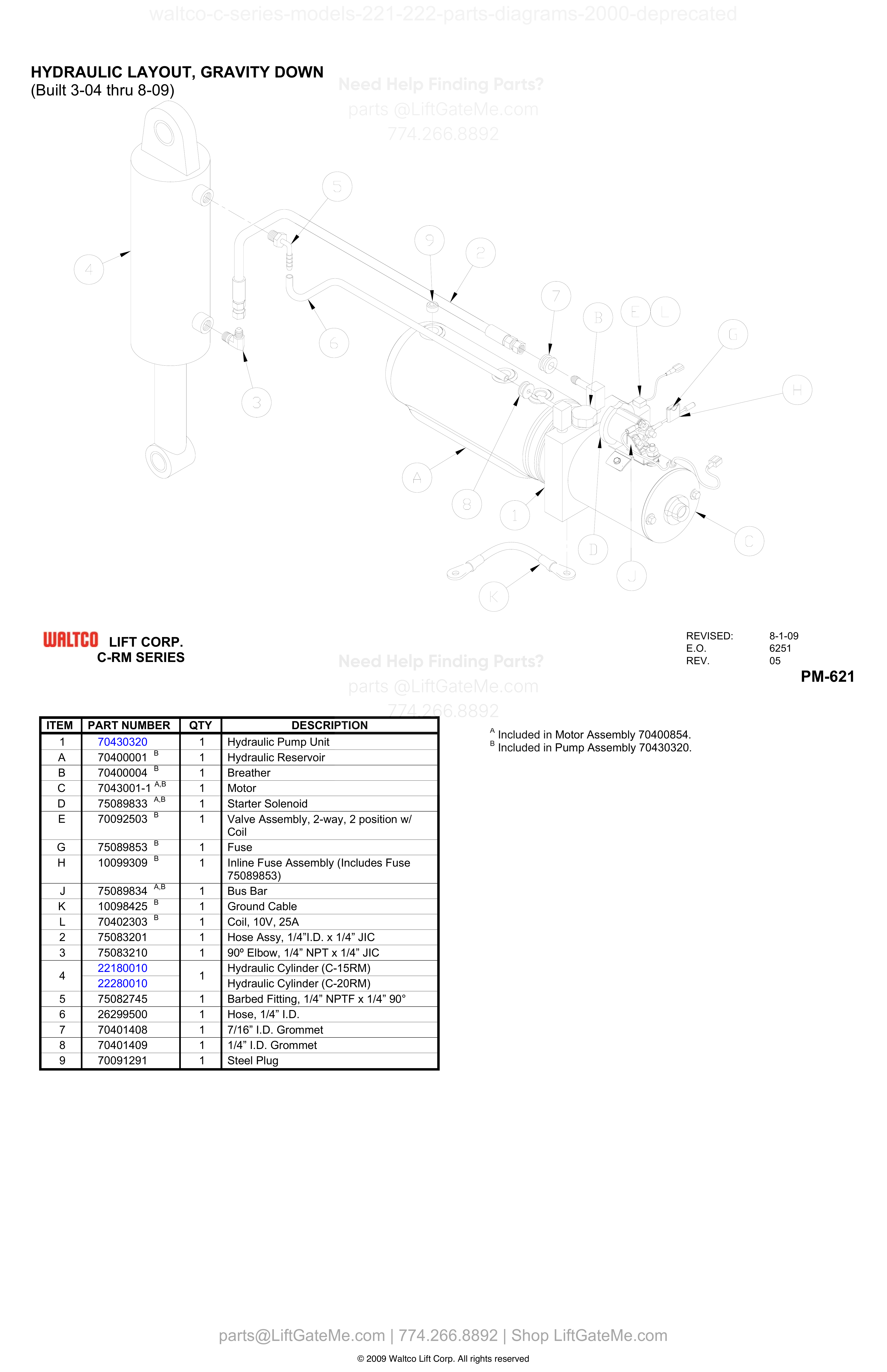
HYDRAULIC LAYOUT, GRAVITY DOWN (Built 3-04 thru 8-09)
| Item | Qty | Part Number | Description | Actions |
|---|---|---|---|---|
| 1 | 1 | 70430320 | Hydraulic Pump Unit | |
| A | 1 | 70400001 B | Hydraulic Reservoir | |
| B | 1 | 70400004 B | Breather | |
| C | 1 | 7043001-1 A,B | Motor | |
| D | 1 | 75089833 A,B | Starter Solenoid | |
| E | 1 | 70092503 B | Valve Assembly, 2-way, 2 position w/ Coil | |
| G | 1 | 75089853 B | Fuse | |
| H | 1 | 10099309 B | Inline Fuse Assembly (Includes Fuse 75089853) | |
| J | 1 | 75089834 A,B | Bus Bar | |
| K | 1 | 10098425 B | Ground Cable | |
| L | 1 | 70402303 B | Coil, 10V, 25A | |
| 2 | 1 | 75083201 | Hose Assy, 1/4”I.D. x 1/4” JIC | |
| 3 | 1 | 75083210 | 90° Elbow, 1/4” NPT x 1/4” JIC | |
| 4 | 1 | 22180010 | Hydraulic Cylinder (C-15RM) | |
| 4 | 1 | 22280010 | Hydraulic Cylinder (C-20RM) | |
| 5 | 1 | 75082745 | Barbed Fitting, 1/4” NPTF x 1/4” 90° | |
| 6 | 1 | 26299500 | Hose, 1/4” I.D. | |
| 7 | 1 | 70401408 | 7/16” I.D. Grommet | |
| 8 | 1 | 70401409 | 1/4” I.D. Grommet | |
| 9 | 1 | 70091291 | Steel Plug |
Reference Notice
Manual links are provided for reference only. If you have any doubt, contact us — we’re happy to verify parts and help you purchase with confidence.
Have your liftgate serial number ready for faster assistance. Where to find it
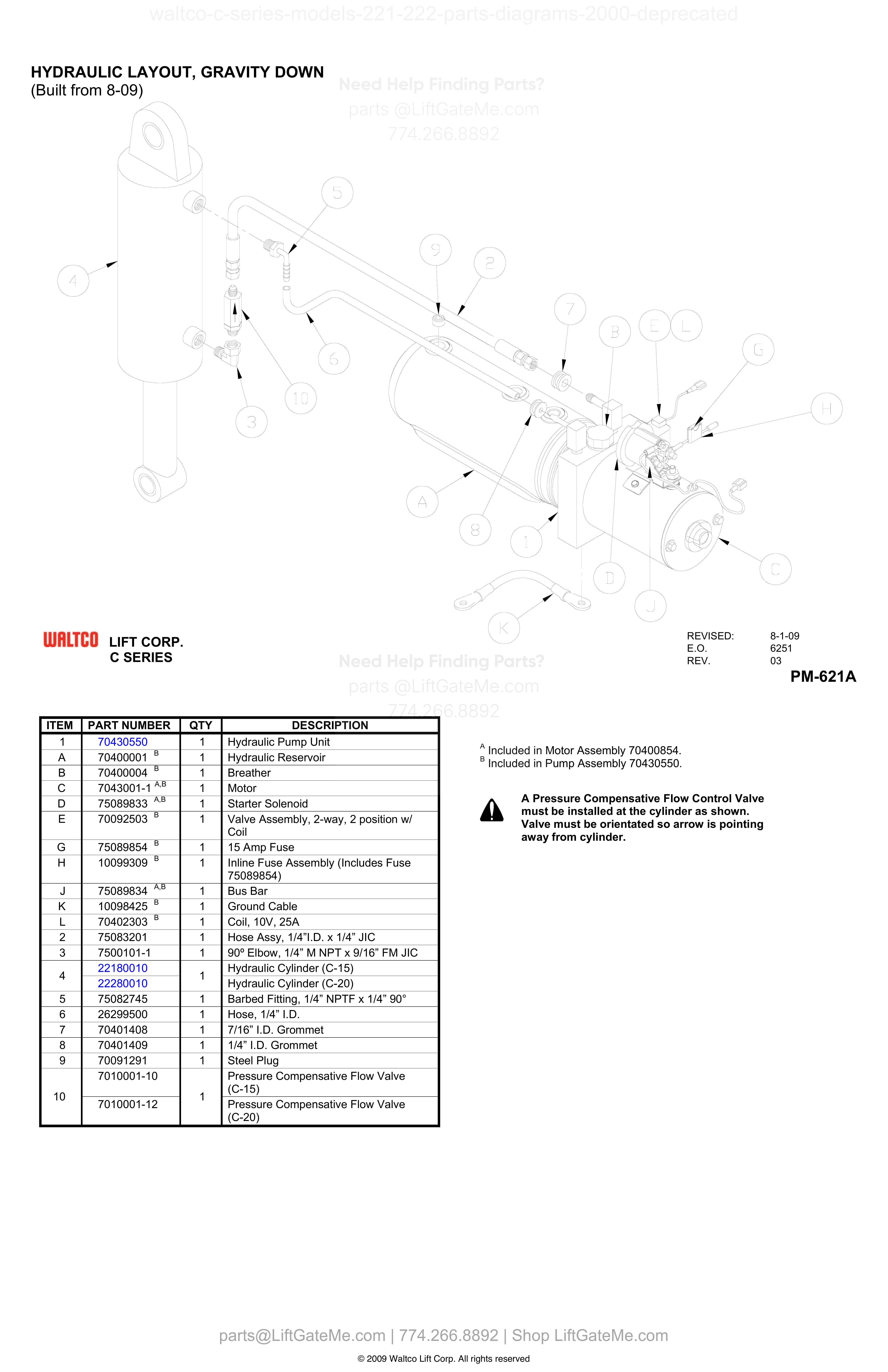
HYDRAULIC LAYOUT, GRAVITY DOWN (Built from 8-09)
| Item | Qty | Part Number | Description | Actions |
|---|---|---|---|---|
| 1 | 1 | 70430550 | Hydraulic Pump Unit | |
| A | 1 | 70400001 B | Hydraulic Reservoir | |
| B | 1 | 70400004 B | Breather | |
| C | 1 | 7043001-1 A,B | Motor | |
| D | 1 | 75089833 A,B | Starter Solenoid | |
| E | 1 | 70092503 B | Valve Assembly, 2-way, 2 position w/ Coil | |
| G | 1 | 75089854 B | 15 Amp Fuse | |
| H | 1 | 10099309 B | Inline Fuse Assembly (Includes Fuse 75089854) | |
| J | 1 | 75089834 A,B | Bus Bar | |
| K | 1 | 10098425 B | Ground Cable | |
| L | 1 | 70402303 B | Coil, 10V, 25A | |
| 2 | 1 | 75083201 | ||
| 3 | 1 | 7500101-1 | ||
| 4 | 1 | 22180010 | Hydraulic Cylinder (C-15) | |
| 4 | 1 | 22280010 | Hydraulic Cylinder (C-20) | |
| 5 | 1 | 75082745 | Barbed Fitting, 1/4” NPTF x 1/4” 90° | |
| 6 | 1 | 26299500 | Hose, 1/4” I.D. | |
| 7 | 1 | 70401408 | 7/16” I.D. Grommet | |
| 8 | 1 | 70401409 | 1/4” I.D. Grommet | |
| 9 | 1 | 70091291 | Steel Plug | |
| 10 | 1 | 7010001-10 | Pressure Compensative Flow Valve (C-15) | |
| 10 | 1 | 7010001-12 | Pressure Compensative Flow Valve (C-20) | |
| 9 | 7010001-10 | Pressure Compensative Flow Valve (C-15) |
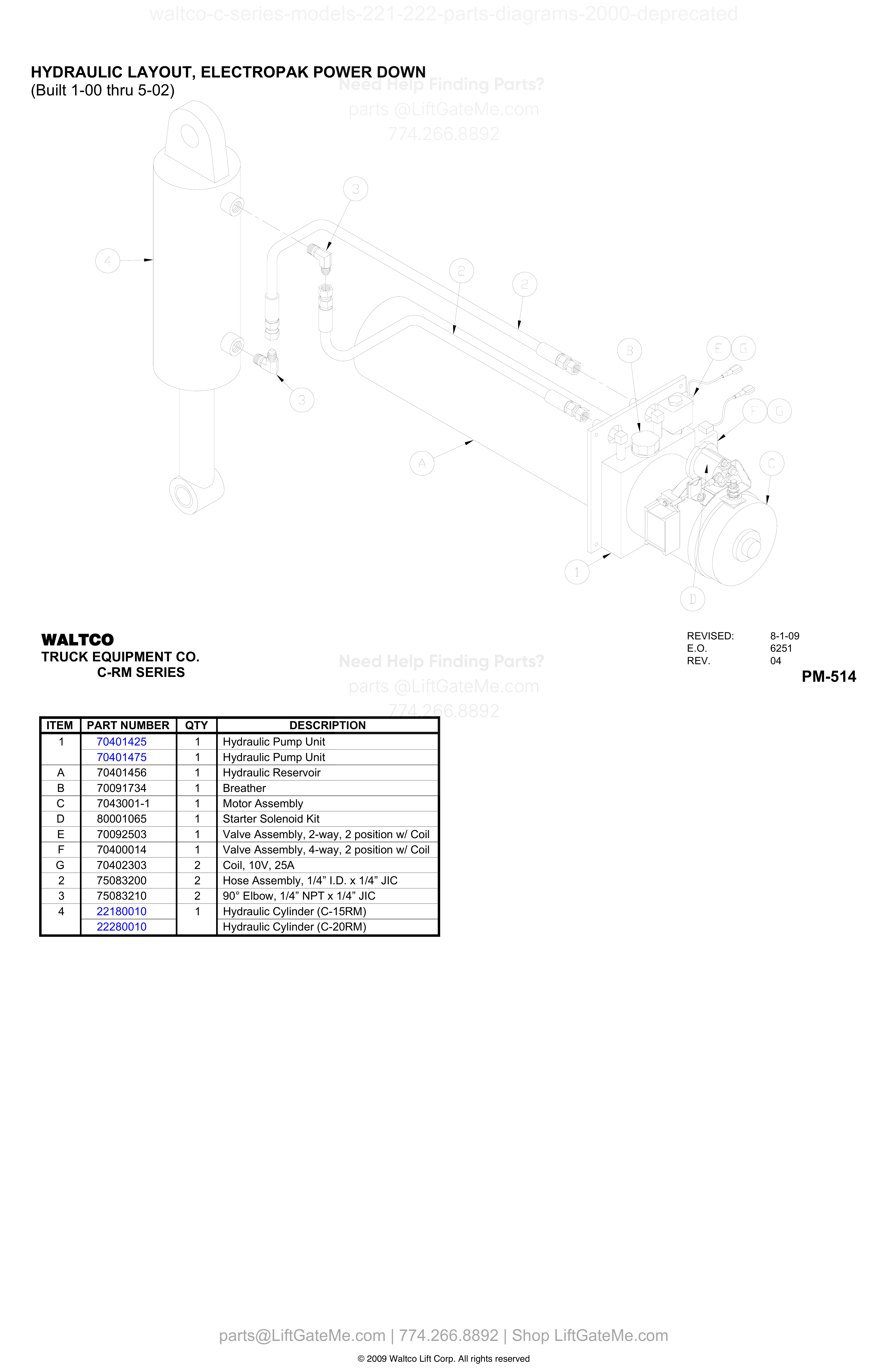
HYDRAULIC LAYOUT, ELECTROPAK POWER DOWN
| Item | Qty | Part Number | Description | Actions |
|---|---|---|---|---|
| 1 | 1 | 70401425 | Hydraulic Pump Unit | |
| 1 | 1 | 70401475 | Hydraulic Pump Unit | |
| A | 1 | 70401456 | Hydraulic Reservoir | |
| B | 1 | 70091734 | Breather | |
| C | 1 | 7043001-1 | Motor Assembly | |
| D | 1 | 80001065 | Starter Solenoid Kit | |
| E | 1 | 70092503 | Valve Assembly, 2-way, 2 position w/ Coil | |
| F | 1 | 70400014 | Valve Assembly, 4-way, 2 position w/ Coil | |
| G | 2 | 70402303 | Coil, 10V, 25A | |
| 2 | 2 | 75083200 | Hose Assembly, 1/4” I.D. x 1/4” JIC | |
| 3 | 2 | 75083210 | 90° Elbow, 1/4” NPT x 1/4” JIC | |
| 4 | 1 | 22180010 | Hydraulic Cylinder (C-15RM) | |
| 4 | 22280010 | Hydraulic Cylinder (C-20RM) |
Reference Notice
Manual links are provided for reference only. If you have any doubt, contact us — we’re happy to verify parts and help you purchase with confidence.
Have your liftgate serial number ready for faster assistance. Where to find it
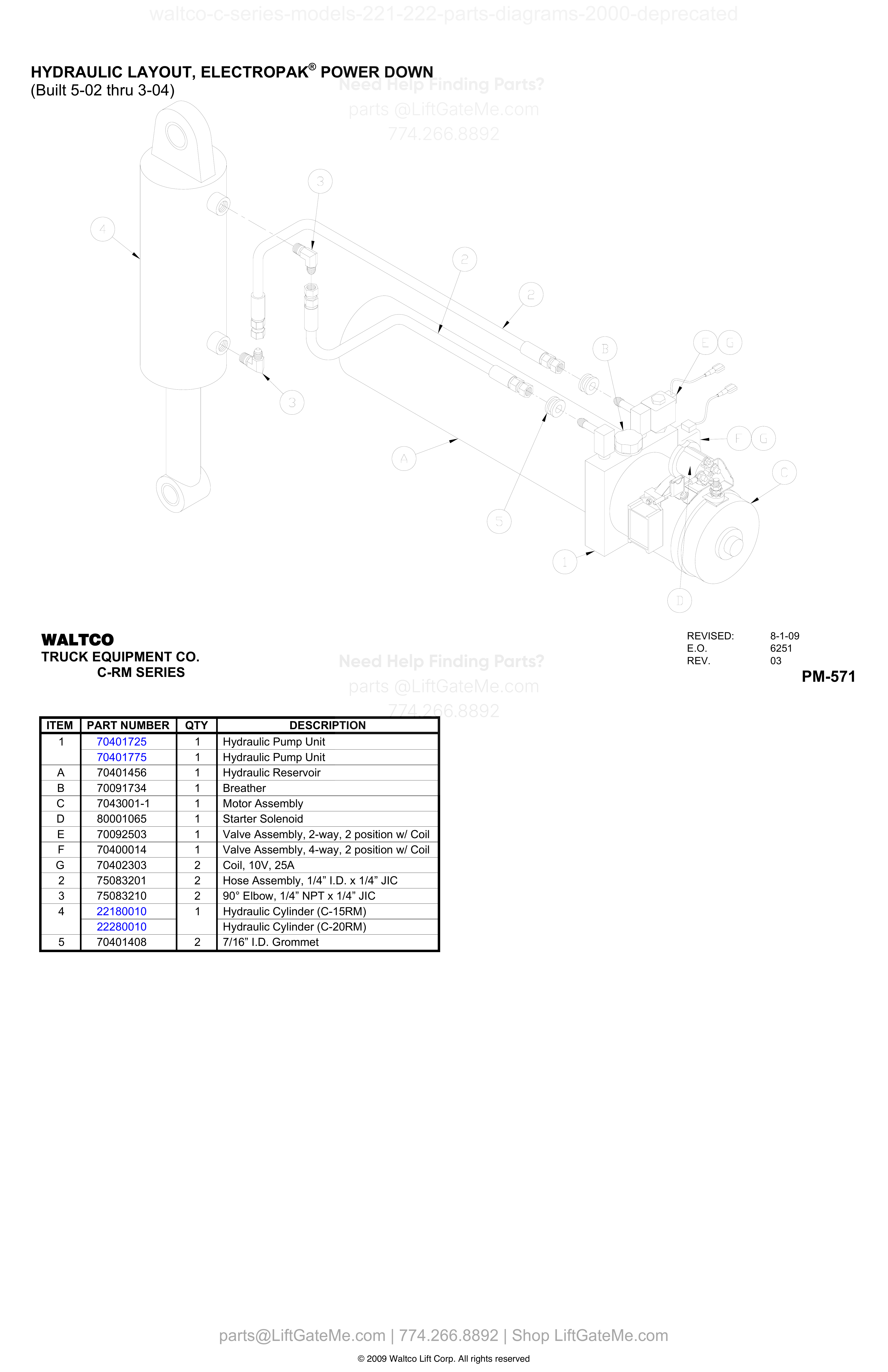
HYDRAULIC LAYOUT, ELECTROPAK® POWER DOWN (Built 5-02 thru 3-04)
| Item | Qty | Part Number | Description | Actions |
|---|---|---|---|---|
| 1 | 1 | 70401725 | Hydraulic Pump Unit | |
| 1 | 1 | 70401775 | Hydraulic Pump Unit | |
| A | 1 | 70401456 | Hydraulic Reservoir | |
| B | 1 | 70091734 | Breather | |
| C | 1 | 7043001-1 | Motor Assembly | |
| D | 1 | 80001065 | Starter Solenoid | |
| E | 1 | 70092503 | Valve Assembly, 2-way, 2 position w/ Coil | |
| F | 1 | 70400014 | Valve Assembly, 4-way, 2 position w/ Coil | |
| G | 2 | 70402303 | Coil, 10V, 25A | |
| 2 | 2 | 75083201 | Hose Assembly, 1/4” I.D. x 1/4” JIC | |
| 3 | 2 | 75083210 | 90° Elbow, 1/4” NPT x 1/4” JIC | |
| 4 | 1 | 22180010 | Hydraulic Cylinder (C-15RM) | |
| 4 | 22280010 | Hydraulic Cylinder (C-20RM) | ||
| 5 | 2 | 70401408 | 7/16” I.D. Grommet |
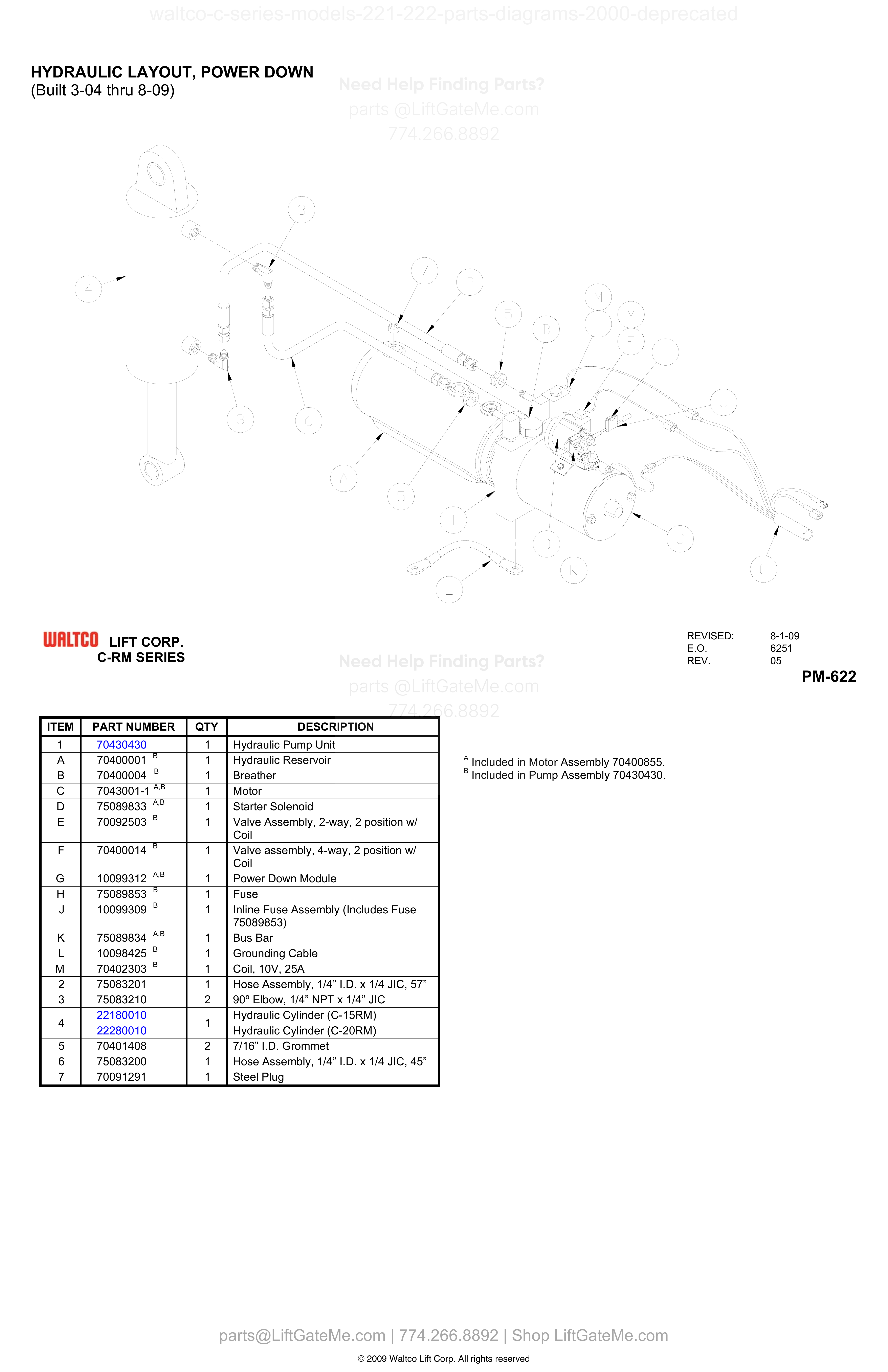
HYDRAULIC LAYOUT, POWER DOWN
| Item | Qty | Part Number | Description | Actions |
|---|---|---|---|---|
| 1 | 1 | 70430430 | Hydraulic Pump Unit | |
| A | 1 | 70400001 B | Hydraulic Reservoir | |
| B | 1 | 70400004 B | Breather | |
| C | 1 | 7043001-1 A,B | Motor | |
| D | 1 | 75089833 A,B | Starter Solenoid | |
| E | 1 | 70092503 B | Valve Assembly, 2-way, 2 position w/ Coil | |
| F | 1 | 70400014 B | Valve assembly, 4-way, 2 position w/ Coil | |
| G | 1 | 10099312 A,B | Power Down Module | |
| H | 1 | 75089853 B | Fuse | |
| J | 1 | 10099309 B | Inline Fuse Assembly (Includes Fuse 75089853) | |
| K | 1 | 75089834 A,B | Bus Bar | |
| L | 1 | 10098425 B | Grounding Cable | |
| M | 1 | 70402303 B | Coil, 10V, 25A | |
| 2 | 1 | 75083201 | Hose Assembly, 1/4” I.D. x 1/4 JIC, 57” | |
| 3 | 2 | 75083210 | ||
| 4 | 1 | 22180010 | Hydraulic Cylinder (C-15RM) | |
| 4 | 1 | 22280010 | Hydraulic Cylinder (C-20RM) | |
| 5 | 2 | 70401408 | 7/16” I.D. Grommet | |
| 6 | 1 | 75083200 | Hose Assembly, 1/4” I.D. x 1/4 JIC, 45” | |
| 7 | 1 | 70091291 | Steel Plug |
Reference Notice
Manual links are provided for reference only. If you have any doubt, contact us — we’re happy to verify parts and help you purchase with confidence.
Have your liftgate serial number ready for faster assistance. Where to find it
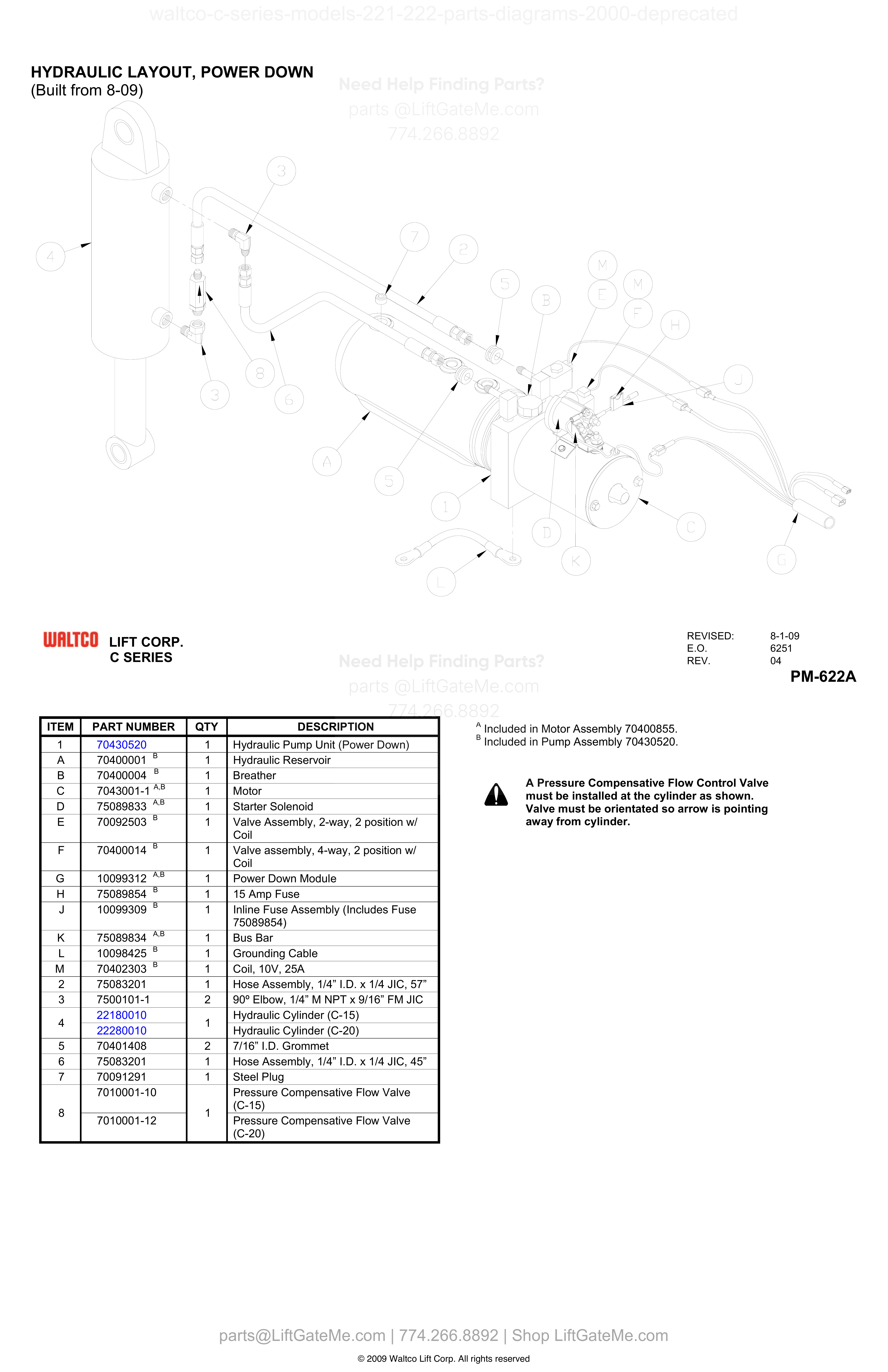
HYDRAULIC LAYOUT, POWER DOWN (Built from 8-09)
| Item | Qty | Part Number | Description | Actions |
|---|---|---|---|---|
| 1 | 1 | 70430520 | Hydraulic Pump Unit (Power Down) | |
| A | 1 | 70400001 B | Hydraulic Reservoir | |
| B | 1 | 70400004 B | Breather | |
| C | 1 | 7043001-1 A,B | Motor | |
| D | 1 | 75089833 A,B | Starter Solenoid | |
| E | 1 | 70092503 B | Valve Assembly, 2-way, 2 position w/ Coil | |
| F | 1 | 70400014 B | Valve assembly, 4-way, 2 position w/ Coil | |
| G | 1 | 10099312 A,B | Power Down Module | |
| H | 1 | 75089854 B | 15 Amp Fuse | |
| J | 1 | 10099309 B | Inline Fuse Assembly (Includes Fuse 75089854) | |
| K | 1 | 75089834 A,B | Bus Bar | |
| L | 1 | 10098425 B | Grounding Cable | |
| M | 1 | 70402303 B | Coil, 10V, 25A | |
| 2 | 1 | 75083201 | Hose Assembly, 1/4” I.D. x 1/4 JIC, 57” | |
| 3 | 2 | 7500101-1 | ||
| 4 | 1 | 22180010 | Hydraulic Cylinder (C-15) | |
| 4 | 1 | 22280010 | Hydraulic Cylinder (C-20) | |
| 5 | 2 | 70401408 | 7/16” I.D. Grommet | |
| 6 | 1 | 75083201 | Hose Assembly, 1/4” I.D. x 1/4 JIC, 45” | |
| 7 | 1 | 70091291 | Steel Plug | |
| 7 | 7010001-10 | Pressure Compensative Flow Valve (C-15) | ||
| 8 | 1 | 7010001-12 | Pressure Compensative Flow Valve (C-20) | |
| 8 | 7010001-10 | Pressure Compensative Flow Valve (C-15) |
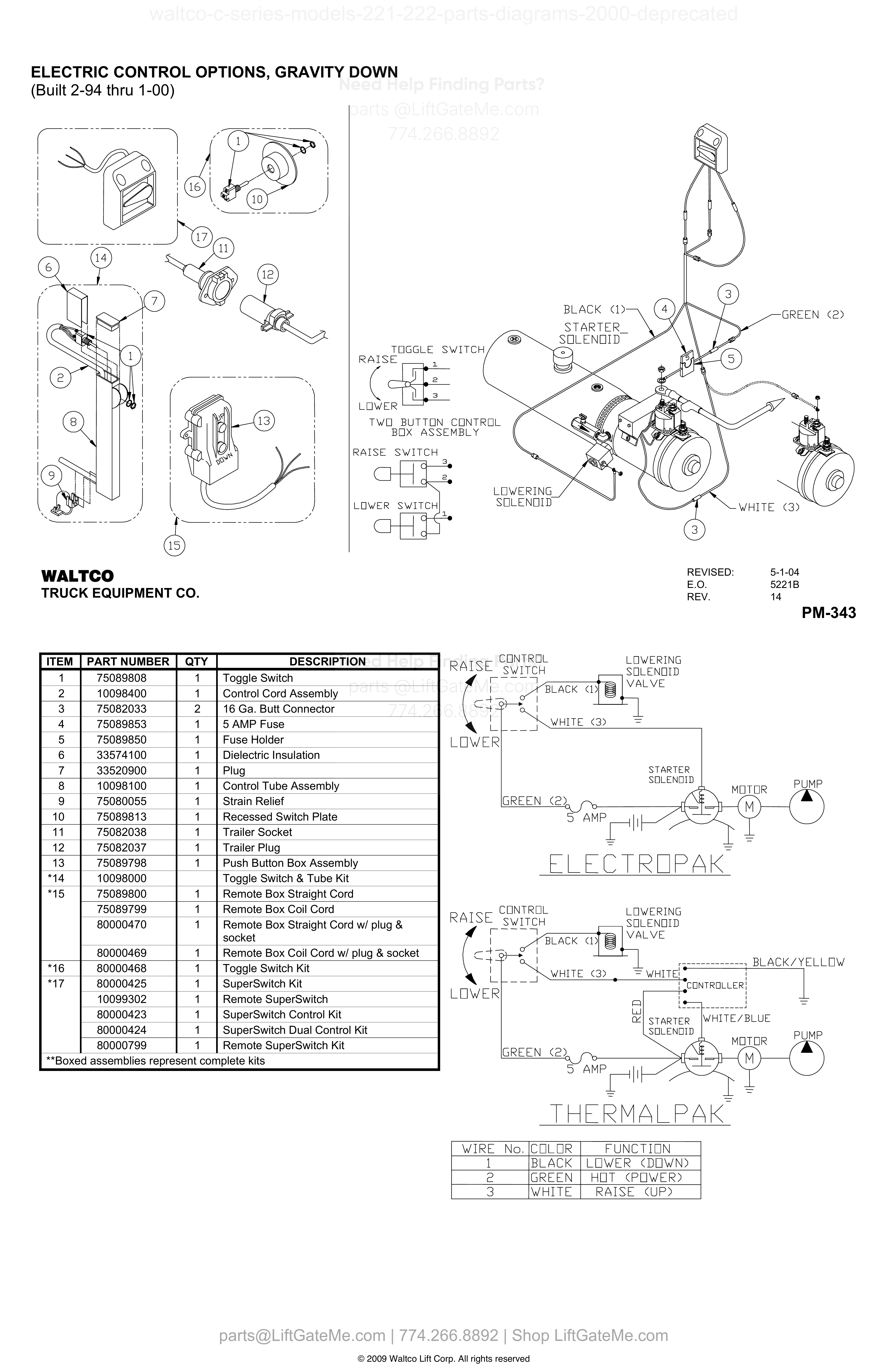
ELECTRIC CONTROL OPTIONS, GRAVITY DOWN
| Item | Qty | Part Number | Description | Actions |
|---|---|---|---|---|
| 1 | 1 | 75089808 | Toggle Switch | |
| 2 | 1 | 10098400 | Control Cord Assembly | |
| 3 | 2 | 75082033 | 16 Ga. Butt Connector | |
| 4 | 1 | 75089853 | 5 AMP Fuse | |
| 5 | 1 | 75089850 | Fuse Holder | |
| 6 | 1 | 33574100 | Dielectric Insulation | |
| 7 | 1 | 33520900 | Plug | |
| 8 | 1 | 10098100 | Control Tube Assembly | |
| 9 | 1 | 75080055 | Strain Relief | |
| 10 | 1 | 75089813 | Recessed Switch Plate | |
| 11 | 1 | 75082038 | Trailer Socket | |
| 12 | 1 | 75082037 | Trailer Plug | |
| 13 | 1 | 75089798 | Push Button Box Assembly | |
| *14 | 10098000 | Toggle Switch & Tube Kit | ||
| *15 | 1 | 75089800 | Remote Box Straight Cord | |
| *15 | 1 | 75089799 | Remote Box Coil Cord | |
| *15 | 1 | 80000470 | Remote Box Straight Cord w/ plug & socket | |
| *15 | 1 | 80000469 | Remote Box Coil Cord w/ plug & socket | |
| *16 | 1 | 80000468 | Toggle Switch Kit | |
| *17 | 1 | 80000425 | SuperSwitch Kit | |
| *17 | 1 | 10099302 | Remote SuperSwitch | |
| *17 | 1 | 80000423 | SuperSwitch Control Kit | |
| *17 | 1 | 80000424 | SuperSwitch Dual Control Kit | |
| *17 | 1 | 80000799 | Remote SuperSwitch Kit |
Reference Notice
Manual links are provided for reference only. If you have any doubt, contact us — we’re happy to verify parts and help you purchase with confidence.
Have your liftgate serial number ready for faster assistance. Where to find it
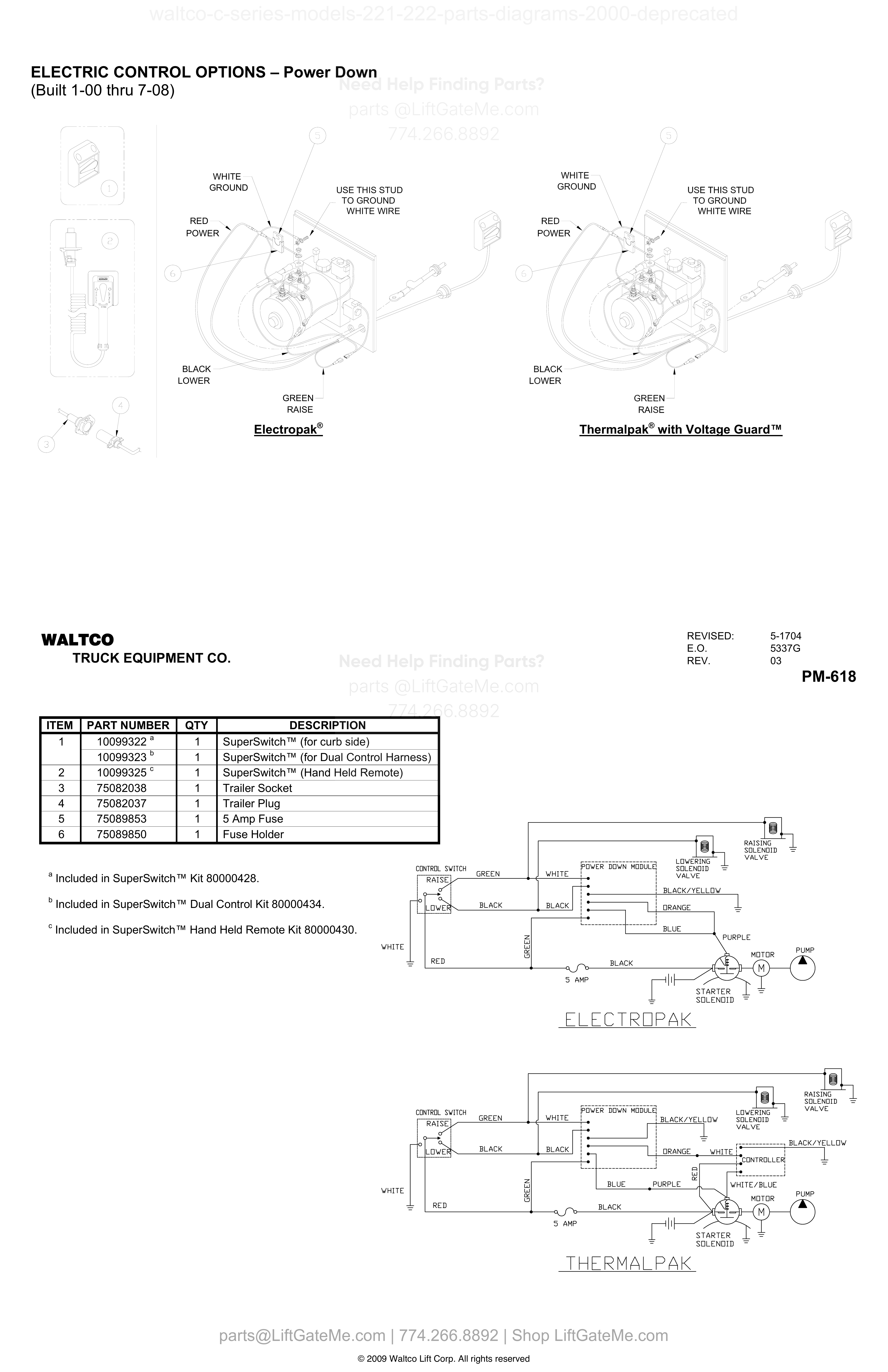
ELECTRIC CONTROL OPTIONS, POWER DOWN
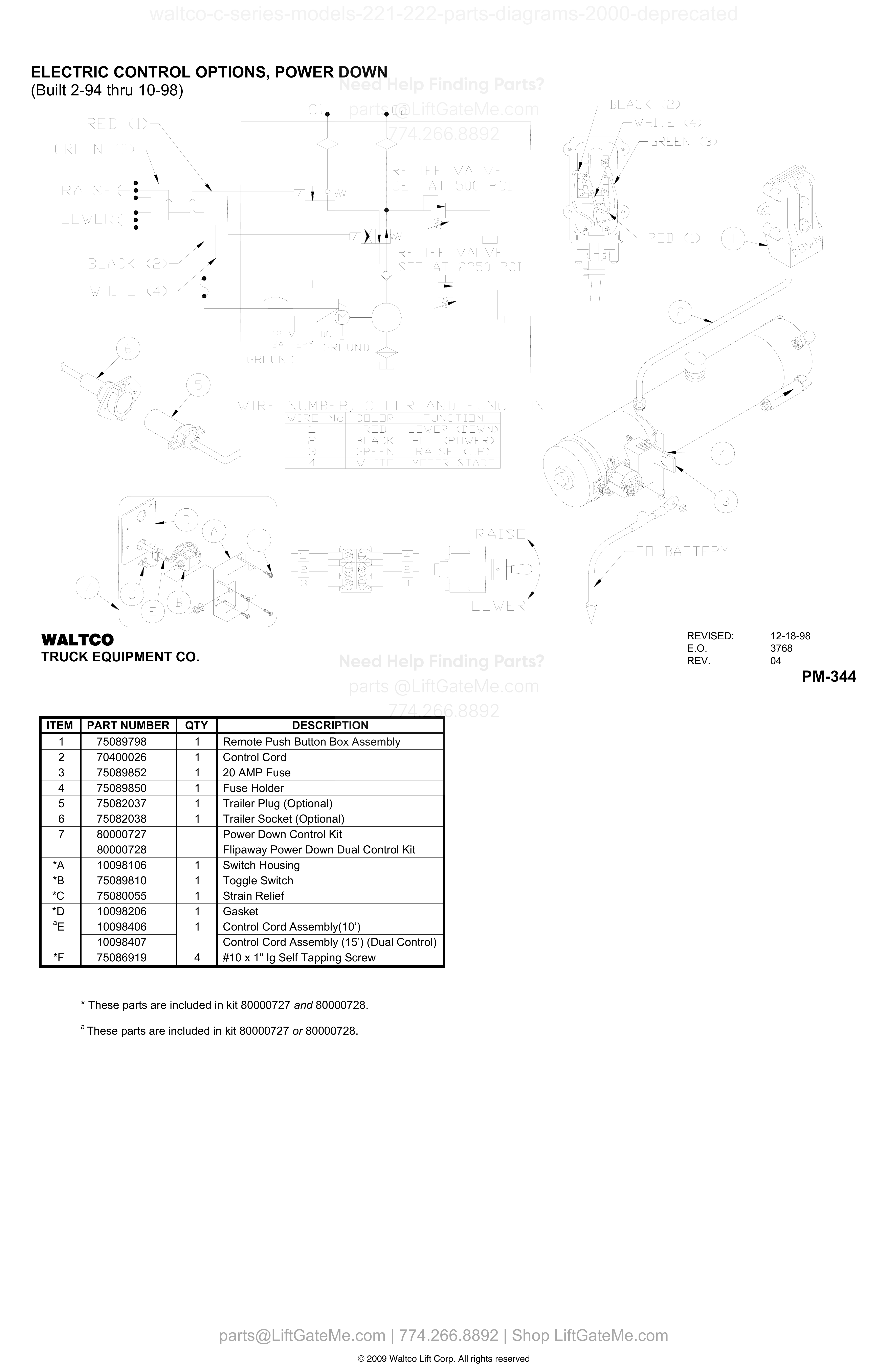
| Item | Qty | Part Number | Description | Actions |
|---|---|---|---|---|
| 1 | 1 | 75089798 | Remote Push Button Box Assembly | |
| 2 | 1 | 70400026 | Control Cord | |
| 3 | 1 | 75089852 | 20 AMP Fuse | |
| 4 | 1 | 75089850 | Fuse Holder | |
| 5 | 1 | 75082037 | Trailer Plug (Optional) | |
| 6 | 1 | 75082038 | Trailer Socket (Optional) | |
| 7 | 80000727 | Power Down Control Kit | ||
| 7 | 80000728 | Flipaway Power Down Dual Control Kit | ||
| *A | 1 | 10098106 | Switch Housing | |
| *B | 1 | 75089810 | Toggle Switch | |
| *C | 1 | 75080055 | Strain Relief | |
| *D | 1 | 10098206 | Gasket | |
| *E | 1 | 10098406 A | Control Cord Assembly(10') | |
| *E | 10098407 | Control Cord Assembly (15') (Dual Control) | ||
| *F | 4 | 75086919 | #10 x 1" lg Self Tapping Screw | |
| aE | 1 | 10098406 | Control Cord Assembly(10') | |
| aE | 10098407 | Control Cord Assembly (15') (Dual Control) |
ELECTRIC CONTROL OPTIONS, POWER DOWN (Built 10-98 thru 1-00)
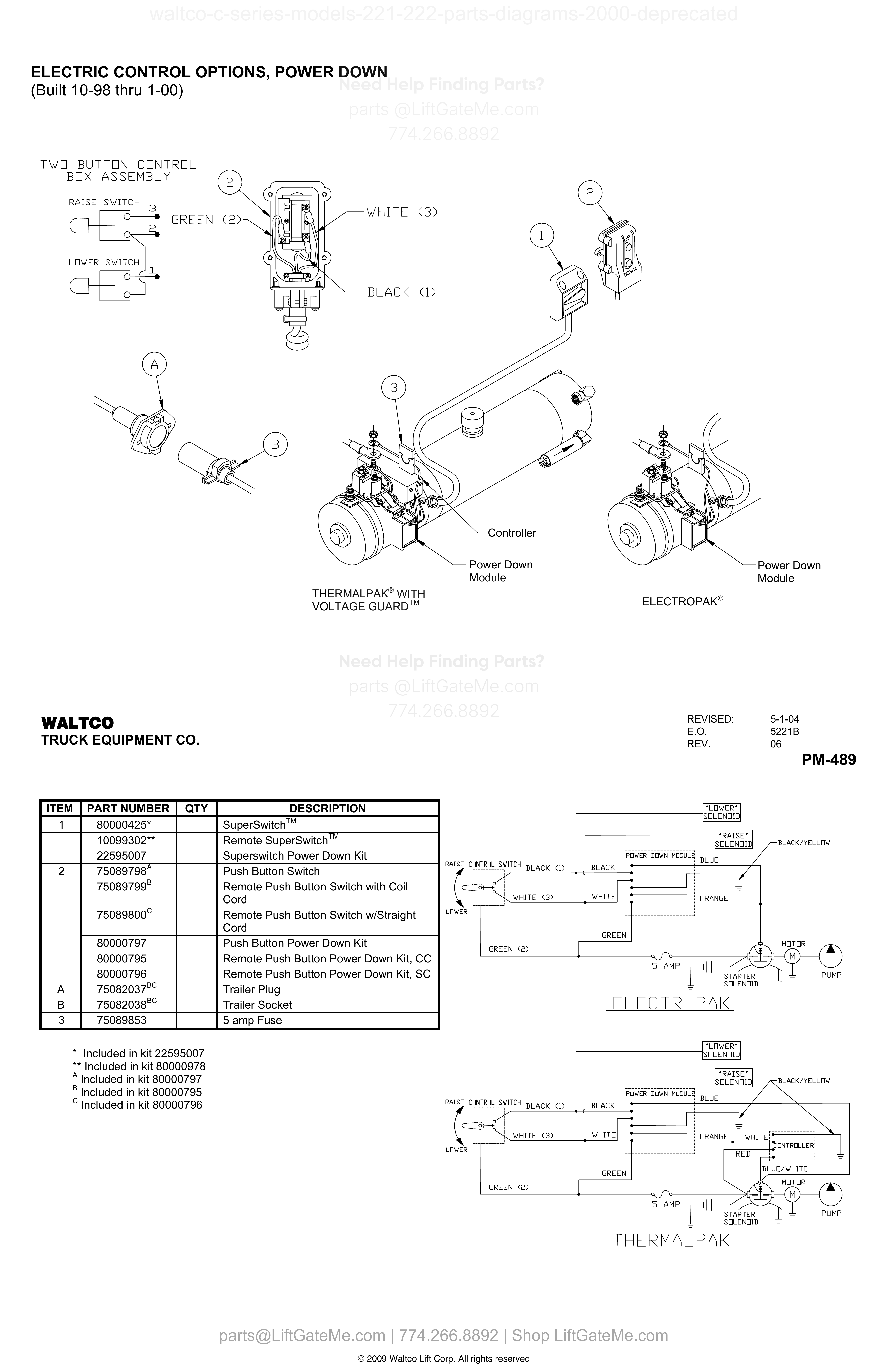
| Item | Qty | Part Number | Description | Actions |
|---|---|---|---|---|
| 1 | 80000425 | SuperSwitchTM | ||
| 1 | 10099302 | Remote SuperSwitchTM | ||
| 1 | 22595007 | Superswitch Power Down Kit | ||
| 2 | 75089798 A | Push Button Switch | ||
| 2 | 75089799 B | Remote Push Button Switch with Coil Cord | ||
| 2 | 75089800 C | Remote Push Button Switch w/Straight Cord | ||
| 2 | 80000797 | Push Button Power Down Kit | ||
| 2 | 80000795 | Remote Push Button Power Down Kit, CC | ||
| 2 | 80000796 | Remote Push Button Power Down Kit, SC | ||
| A | 75082037 B,C | Trailer Plug | ||
| B | 75082038 B,C | Trailer Socket | ||
| 3 | 75089853 | 5 amp Fuse |
Reference Notice
Manual links are provided for reference only. If you have any doubt, contact us — we’re happy to verify parts and help you purchase with confidence.
Have your liftgate serial number ready for faster assistance. Where to find it
ELECTRIC CONTROL OPTIONS – Gravity Down
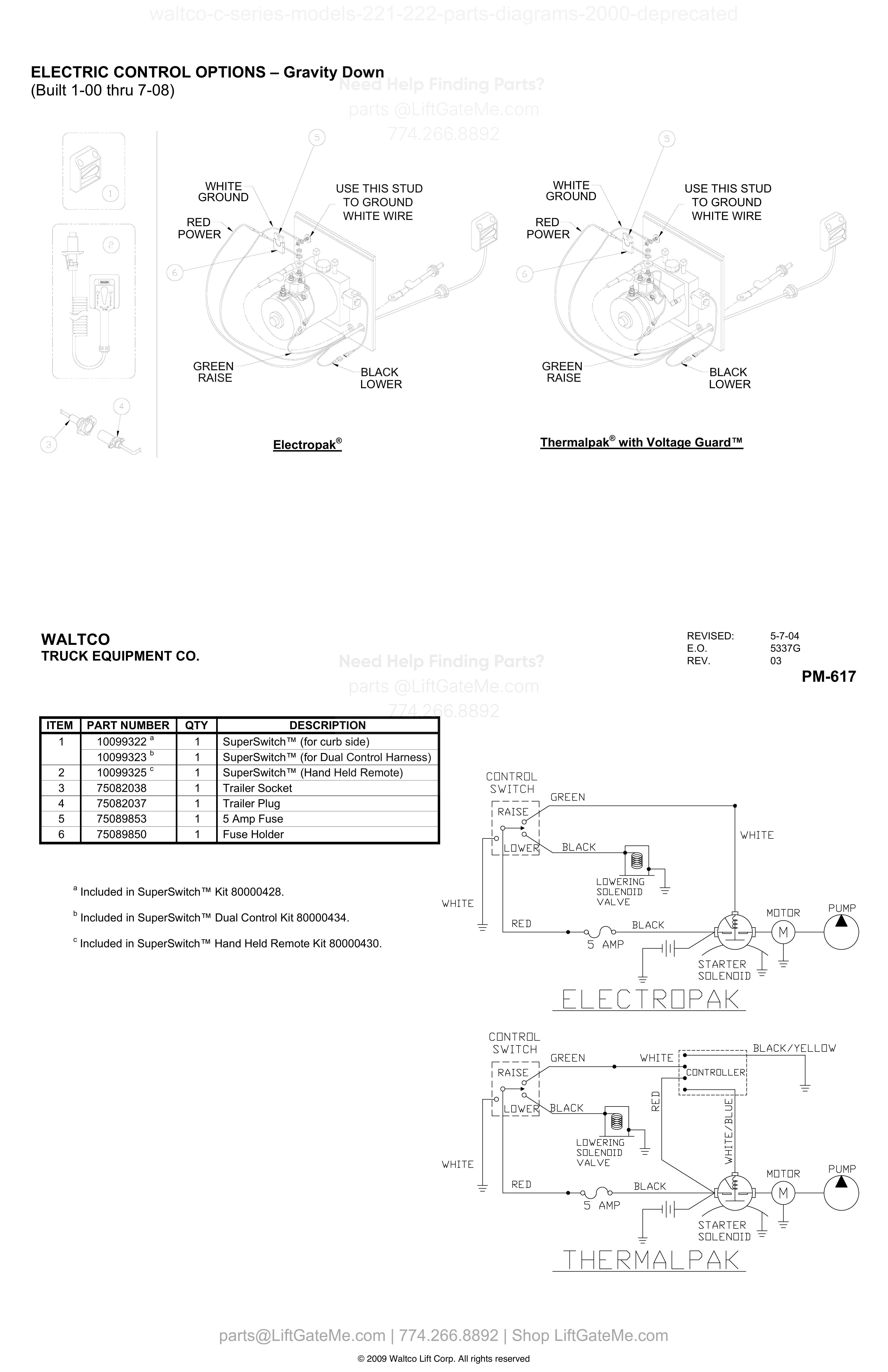
| Item | Qty | Part Number | Description | Actions |
|---|---|---|---|---|
| 1 | 1 | 10099322 A | SuperSwitch™ (for curb side) | |
| 1 | 1 | 10099323 B | SuperSwitch™ (for Dual Control Harness) | |
| 2 | 1 | 10099325 C | SuperSwitch™ (Hand Held Remote) | |
| 3 | 1 | 75082038 | Trailer Socket | |
| 4 | 1 | 75082037 | Trailer Plug | |
| 5 | 1 | 75089853 | 5 Amp Fuse | |
| 6 | 1 | 75089850 | Fuse Holder |
ELECTRIC CONTROL OPTIONS – Gravity Down (Built from 7-08 thru 8-09)
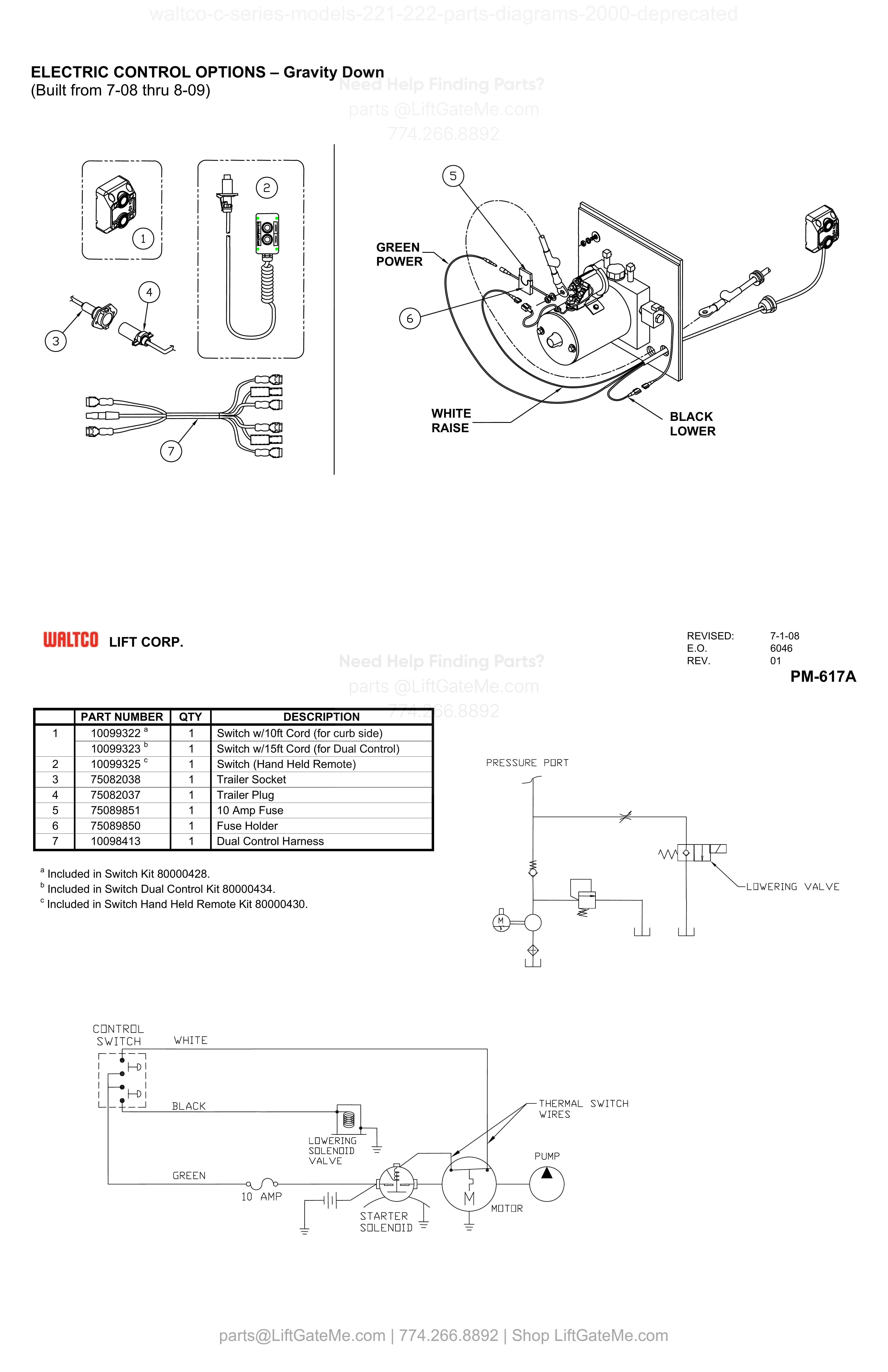
| Item | Qty | Part Number | Description | Actions |
|---|---|---|---|---|
| 1 | 1 | 10099322 A | Switch w/10ft Cord (for curb side) | |
| 1 | 1 | 10099323 B | Switch w/15ft Cord (for Dual Control) | |
| 2 | 1 | 10099325 C | Switch (Hand Held Remote) | |
| 3 | 1 | 75082038 | Trailer Socket | |
| 4 | 1 | 75082037 | Trailer Plug | |
| 5 | 1 | 75089851 | 10 Amp Fuse | |
| 6 | 1 | 75089850 | Fuse Holder | |
| 7 | 1 | 10098413 | Dual Control Harness |
Reference Notice
Manual links are provided for reference only. If you have any doubt, contact us — we’re happy to verify parts and help you purchase with confidence.
Have your liftgate serial number ready for faster assistance. Where to find it
ELECTRIC CONTROL OPTIONS – GRAVITY DOWN (Built from 8-09)
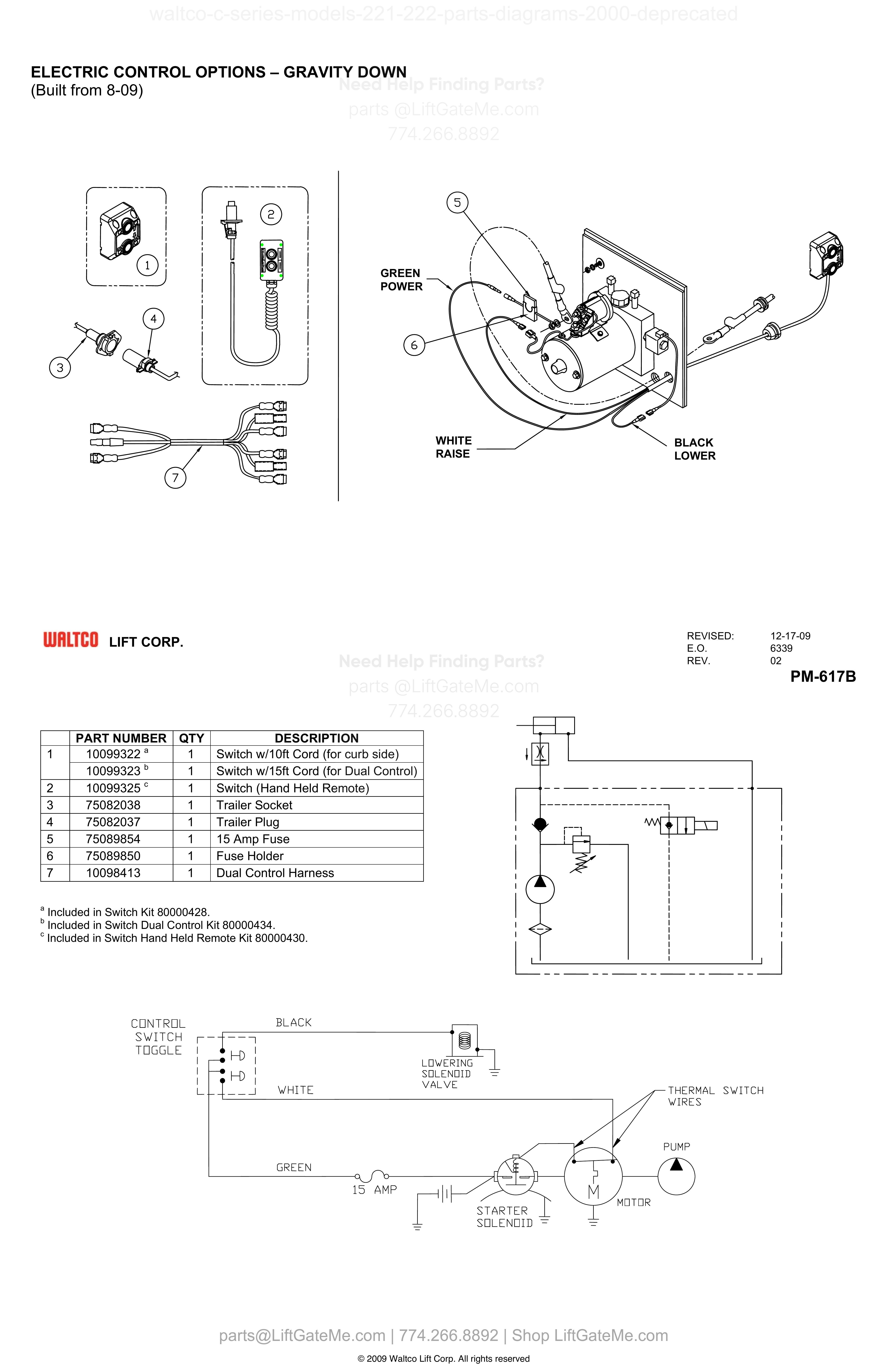
| Item | Qty | Part Number | Description | Actions |
|---|---|---|---|---|
| 1 | 1 | 10099322 A | Switch w/10ft Cord (for curb side) | |
| 1 | 1 | 10099323 B | Switch w/15ft Cord (for Dual Control) | |
| 2 | 1 | 10099325 C | Switch (Hand Held Remote) | |
| 3 | 1 | 75082038 | Trailer Socket | |
| 4 | 1 | 75082037 | Trailer Plug | |
| 5 | 1 | 75089854 | 15 Amp Fuse | |
| 6 | 1 | 75089850 | Fuse Holder | |
| 7 | 1 | 10098413 | Dual Control Harness |
ELECTRIC CONTROL OPTIONS – Power Down
| Item | Qty | Part Number | Description | Actions |
|---|---|---|---|---|
| 1 | 1 | 10099322 A | SuperSwitch™ (for curb side) | |
| 1 | 1 | 10099323 B | SuperSwitch™ (for Dual Control Harness) | |
| 2 | 1 | 10099325 C | SuperSwitch™ (Hand Held Remote) | |
| 3 | 1 | 75082038 | Trailer Socket | |
| 4 | 1 | 75082037 | Trailer Plug | |
| 5 | 1 | 75089853 | 5 Amp Fuse | |
| 6 | 1 | 75089850 | Fuse Holder |
Reference Notice
Manual links are provided for reference only. If you have any doubt, contact us — we’re happy to verify parts and help you purchase with confidence.
Have your liftgate serial number ready for faster assistance. Where to find it
ELECTRIC CONTROL OPTIONS – Power Down (Built 7-08 thru 10-08)
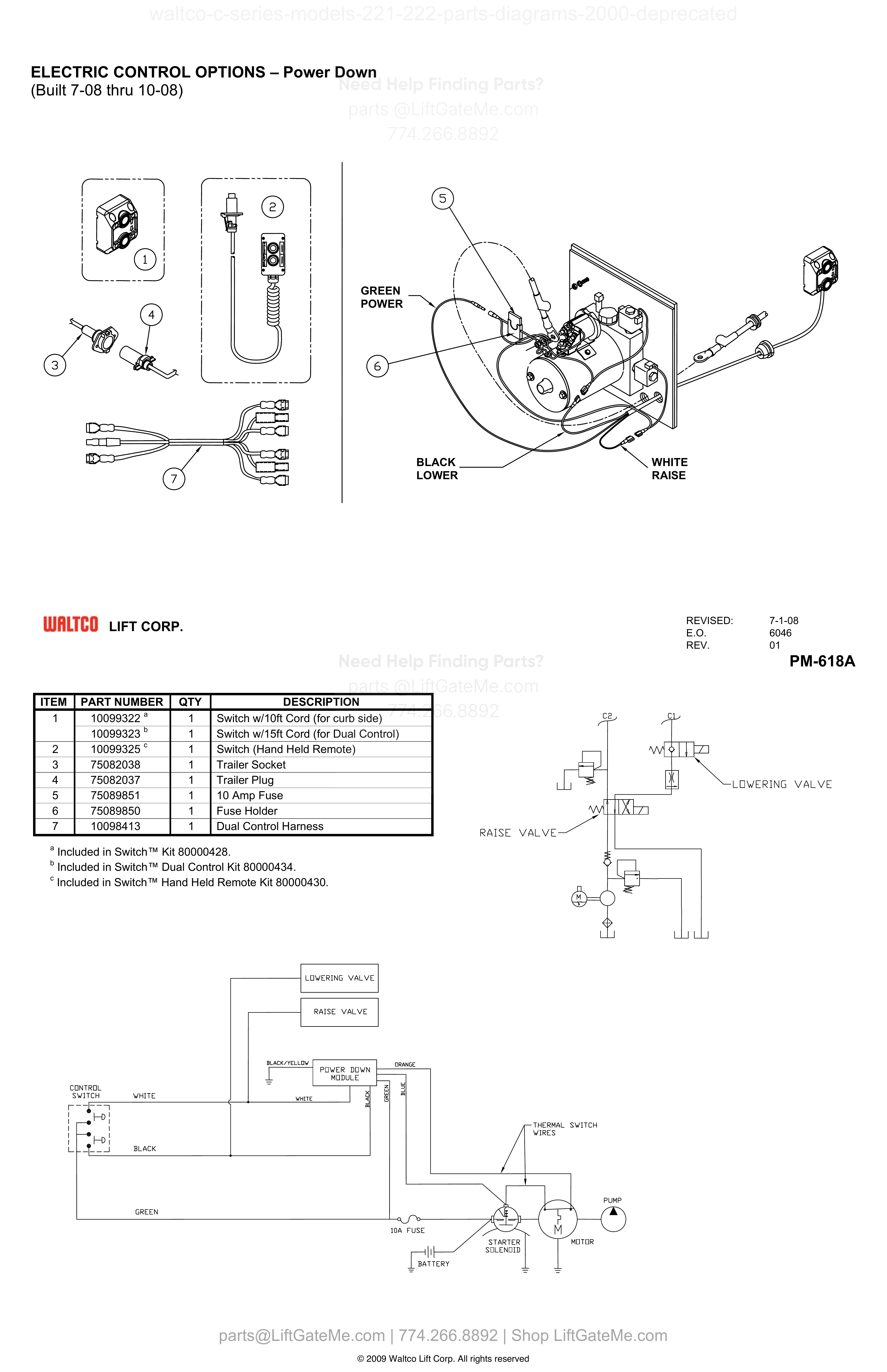
| Item | Qty | Part Number | Description | Actions |
|---|---|---|---|---|
| 1 | 1 | 10099322 A | Switch w/10ft Cord (for curb side) | |
| 1 | 1 | 10099323 B | Switch w/15ft Cord (for Dual Control) | |
| 2 | 1 | 10099325 C | Switch (Hand Held Remote) | |
| 3 | 1 | 75082038 | Trailer Socket | |
| 4 | 1 | 75082037 | Trailer Plug | |
| 5 | 1 | 75089851 | 10 Amp Fuse | |
| 6 | 1 | 75089850 | Fuse Holder | |
| 7 | 1 | 10098413 | Dual Control Harness |
ELECTRIC CONTROL OPTIONS – Power Down
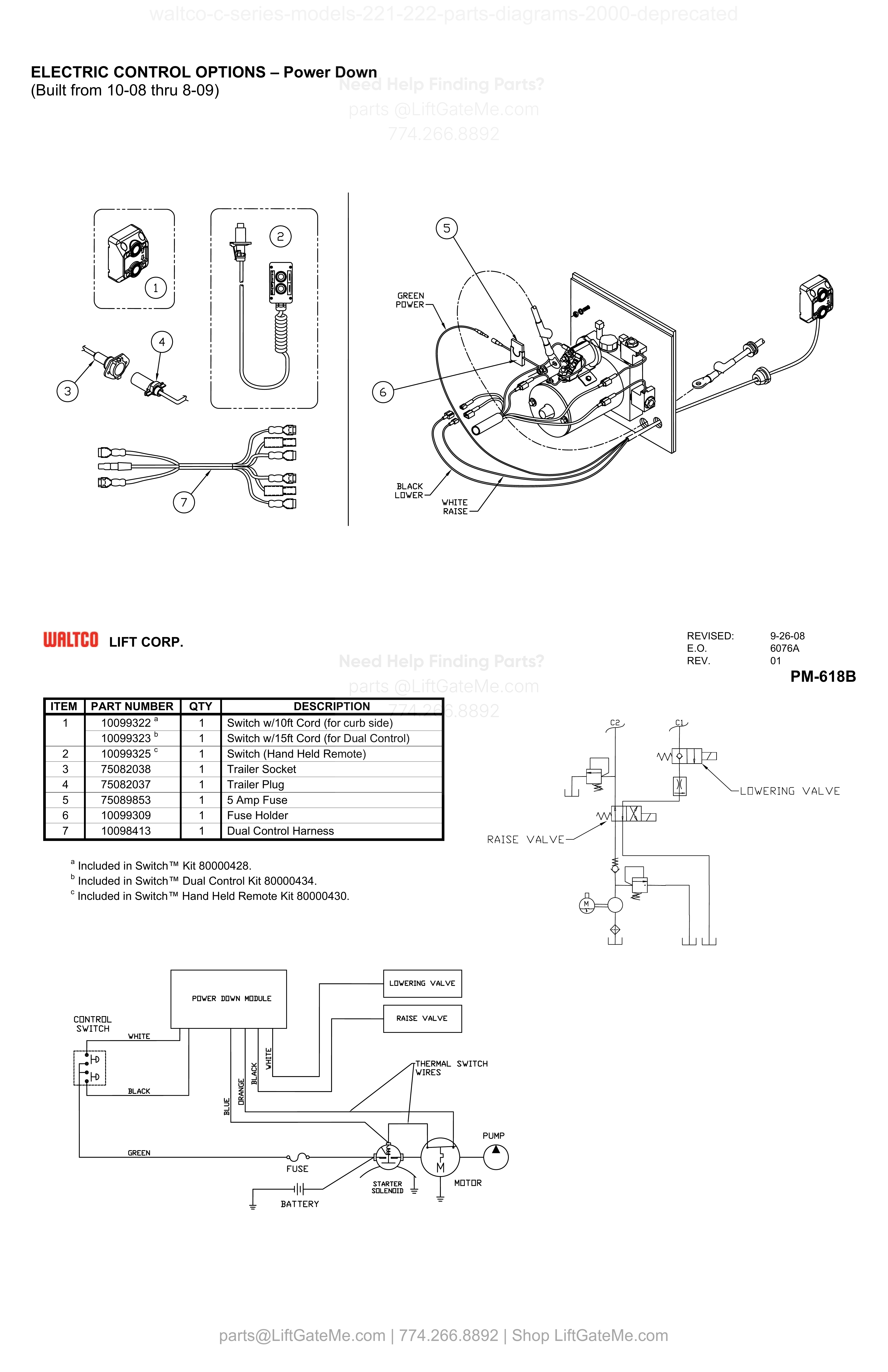
| Item | Qty | Part Number | Description | Actions |
|---|---|---|---|---|
| 1 | 1 | 10099322 A | Switch w/10ft Cord (for curb side) | |
| 1 | 1 | 10099323 B | Switch w/15ft Cord (for Dual Control) | |
| 2 | 1 | 10099325 C | Switch (Hand Held Remote) | |
| 3 | 1 | 75082038 | Trailer Socket | |
| 4 | 1 | 75082037 | Trailer Plug | |
| 5 | 1 | 75089853 | 5 Amp Fuse | |
| 6 | 1 | 10099309 | Fuse Holder | |
| 7 | 1 | 10098413 | Dual Control Harness |
Reference Notice
Manual links are provided for reference only. If you have any doubt, contact us — we’re happy to verify parts and help you purchase with confidence.
Have your liftgate serial number ready for faster assistance. Where to find it
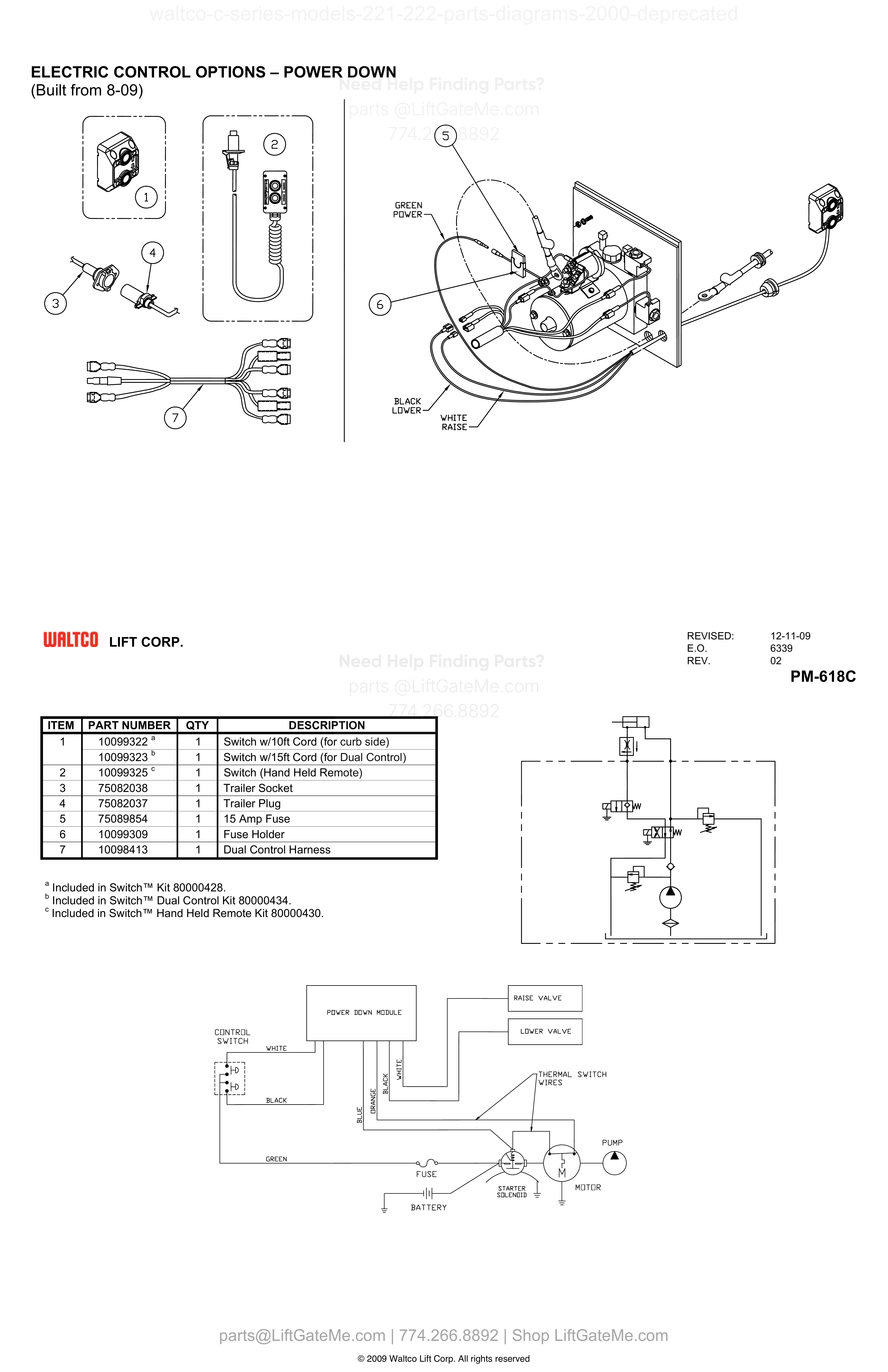
ELECTRIC CONTROL OPTIONS – POWER DOWN (Built from 8-09)
| Item | Qty | Part Number | Description | Actions |
|---|---|---|---|---|
| 1 | 1 | 10099322 A | Switch w/10ft Cord (for curb side) | |
| 1 | 1 | 10099323 B | Switch w/15ft Cord (for Dual Control) | |
| 2 | 1 | 10099325 C | Switch (Hand Held Remote) | |
| 3 | 1 | 75082038 | Trailer Socket | |
| 4 | 1 | 75082037 | Trailer Plug | |
| 5 | 1 | 75089854 | 15 Amp Fuse | |
| 6 | 1 | 10099309 | Fuse Holder | |
| 7 | 1 | 10098413 | Dual Control Harness |
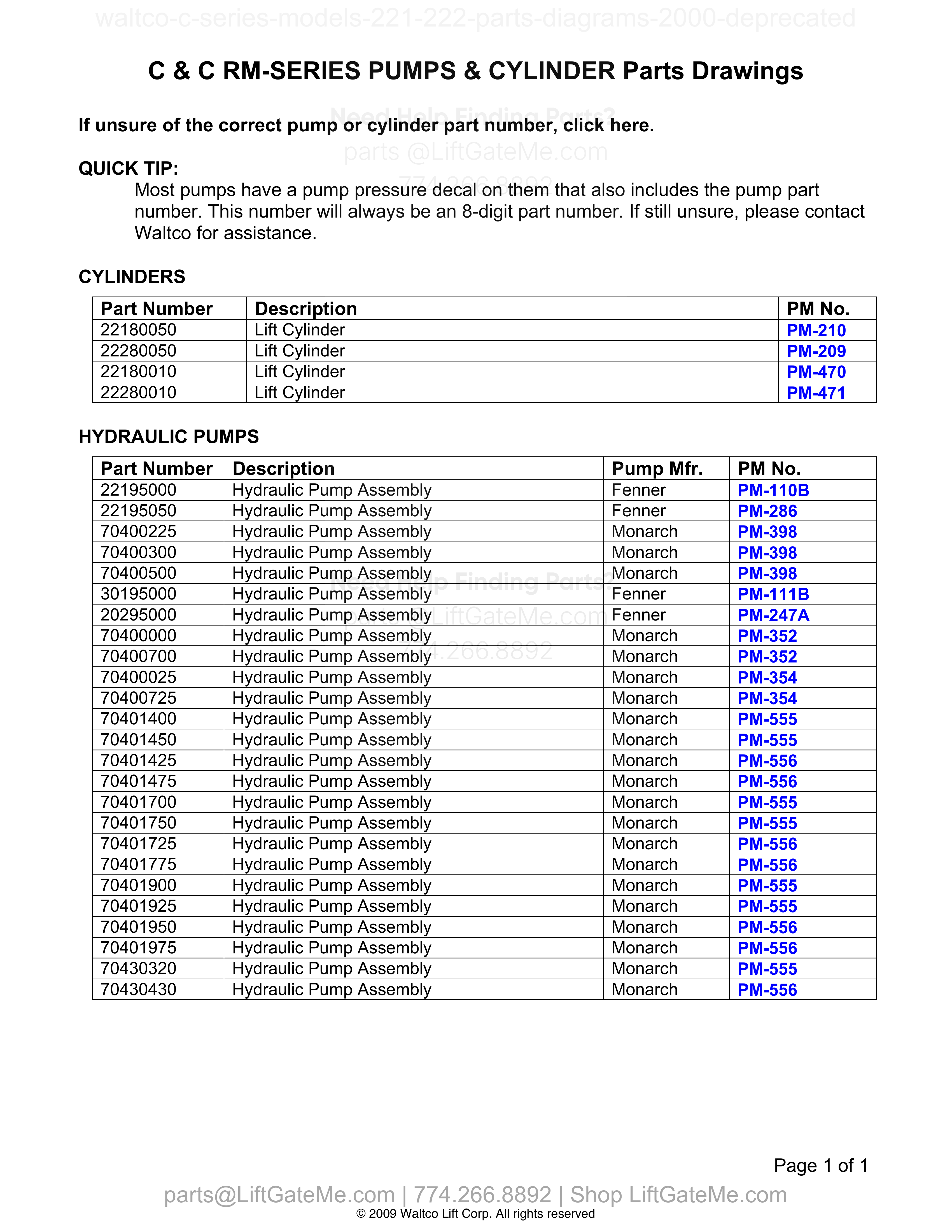
C & C RM-SERIES PUMPS & CYLINDER Parts Drawings
| Item | Qty | Part Number | Description | Actions |
|---|---|---|---|---|
| 22180050 | Lift Cylinder | |||
| 22280050 | Lift Cylinder | |||
| 22180010 | Lift Cylinder | |||
| 22280010 | Lift Cylinder | |||
| 22195000 | Hydraulic Pump Assembly | |||
| 22195050 | Hydraulic Pump Assembly | |||
| 70400225 | Hydraulic Pump Assembly | |||
| 70400300 | Hydraulic Pump Assembly | |||
| 70400500 | Hydraulic Pump Assembly | |||
| 30195000 | Hydraulic Pump Assembly | |||
| 20295000 | Hydraulic Pump Assembly | |||
| 70400000 | Hydraulic Pump Assembly | |||
| 70400700 | Hydraulic Pump Assembly | |||
| 70400025 | Hydraulic Pump Assembly | |||
| 70400725 | Hydraulic Pump Assembly | |||
| 70401400 | Hydraulic Pump Assembly | |||
| 70401450 | Hydraulic Pump Assembly | |||
| 70401425 | Hydraulic Pump Assembly | |||
| 70401475 | Hydraulic Pump Assembly | |||
| 70401700 | Hydraulic Pump Assembly | |||
| 70401750 | Hydraulic Pump Assembly | |||
| 70401725 | Hydraulic Pump Assembly | |||
| 70401775 | Hydraulic Pump Assembly | |||
| 70401900 | Hydraulic Pump Assembly | |||
| 70401925 | Hydraulic Pump Assembly | |||
| 70401950 | Hydraulic Pump Assembly | |||
| 70401975 | Hydraulic Pump Assembly | |||
| 70430320 | Hydraulic Pump Assembly | |||
| 70430430 | Hydraulic Pump Assembly |
Reference Notice
Manual links are provided for reference only. If you have any doubt, contact us — we’re happy to verify parts and help you purchase with confidence.
Have your liftgate serial number ready for faster assistance. Where to find it
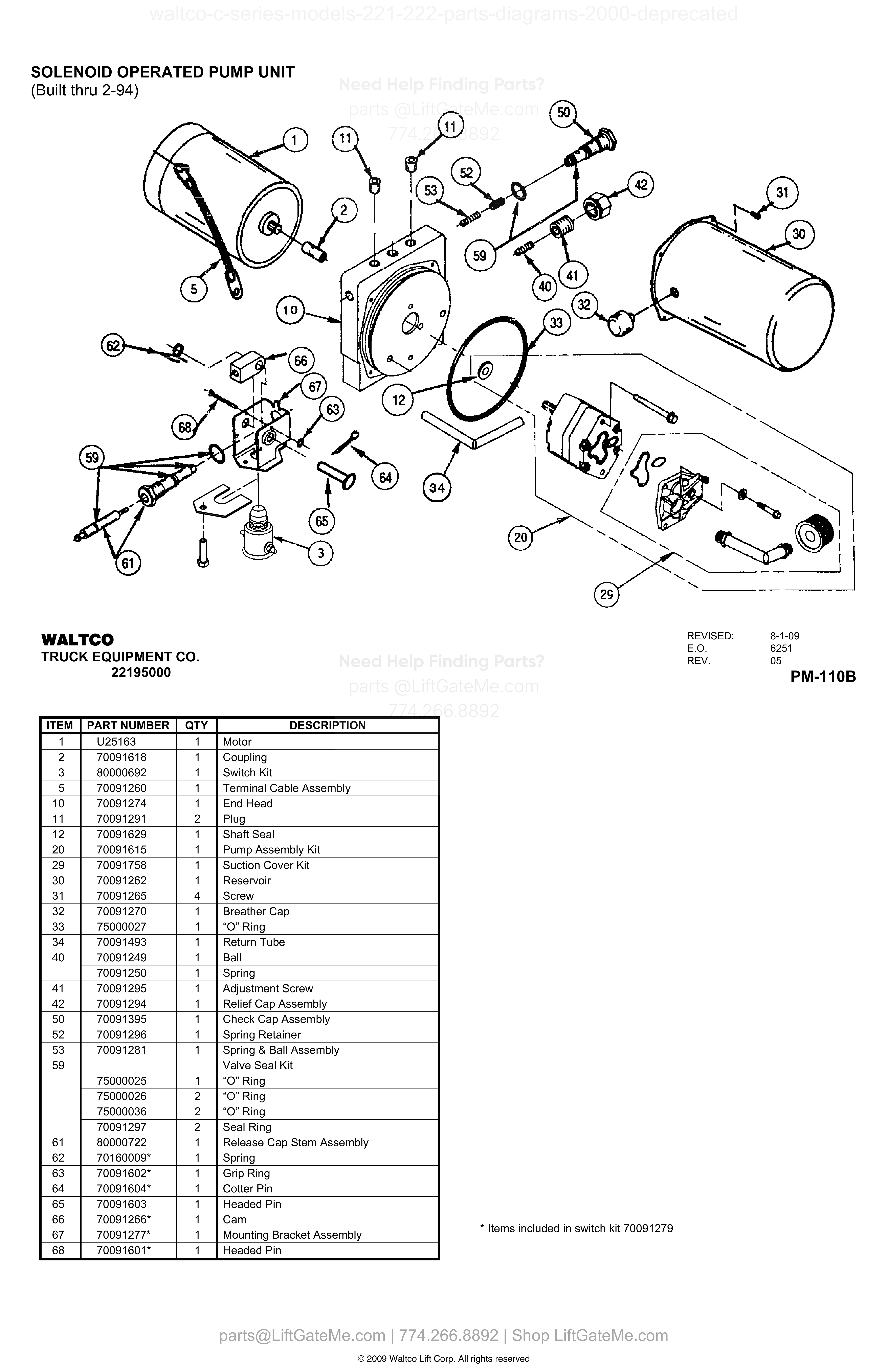
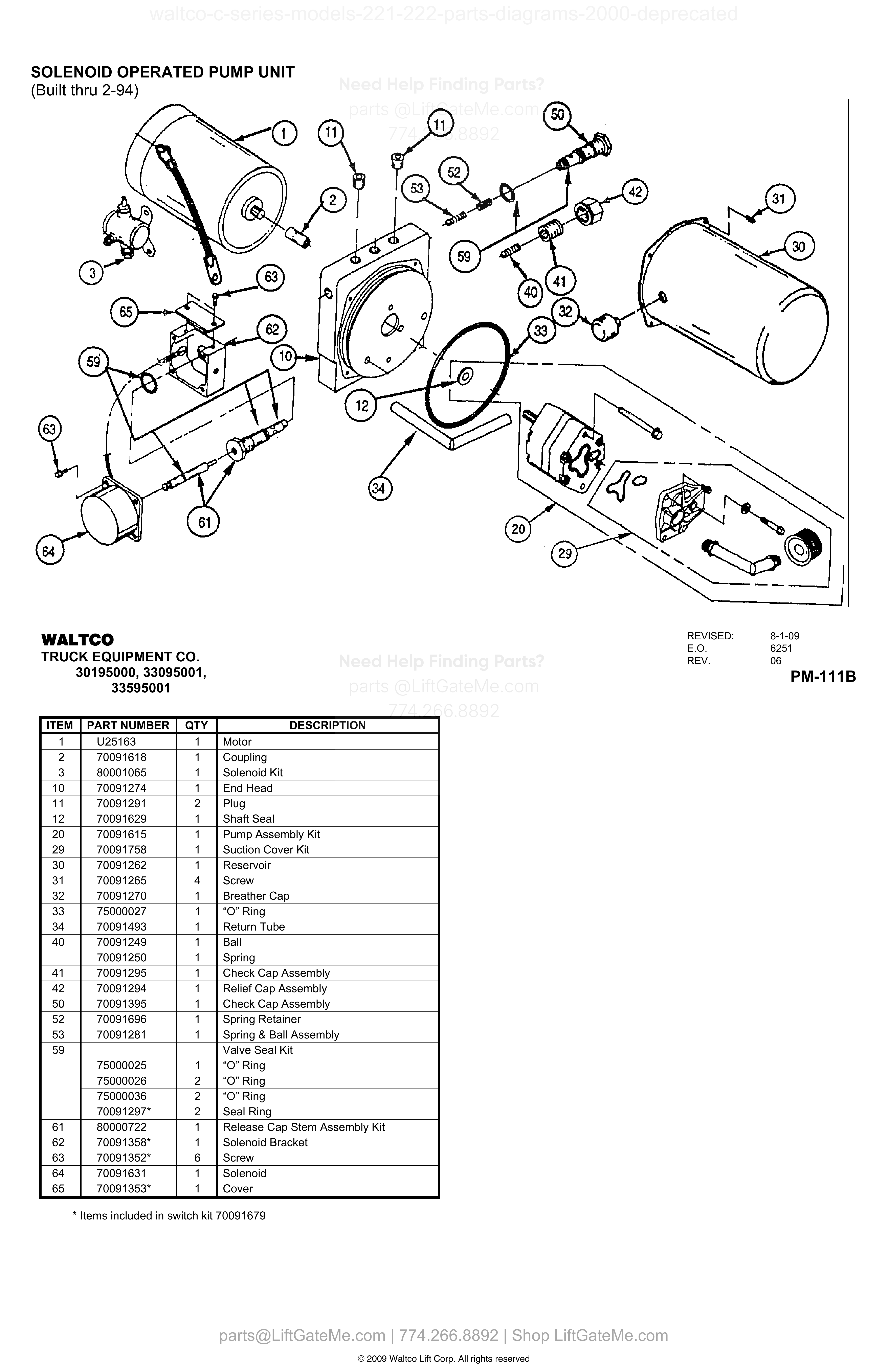
SOLENOID OPERATED PUMP UNIT (Built thru 2-94)
| Item | Qty | Part Number | Description | Actions |
|---|---|---|---|---|
| 1 | 1 | U25163 | Motor | |
| 2 | 1 | 70091618 | Coupling | |
| 3 | 1 | 80000692 | Switch Kit | |
| 5 | 1 | 70091260 | Terminal Cable Assembly | |
| 10 | 1 | 70091274 | End Head | |
| 11 | 2 | 70091291 | Plug | |
| 12 | 1 | 70091629 | Shaft Seal | |
| 20 | 1 | 70091615 | Pump Assembly Kit | |
| 29 | 1 | 70091758 | Suction Cover Kit | |
| 30 | 1 | 70091262 | Reservoir | |
| 31 | 4 | 70091265 | Screw | |
| 32 | 1 | 70091270 | Breather Cap | |
| 33 | 1 | 75000027 | “O” Ring | |
| 34 | 1 | 70091493 | Return Tube | |
| 40 | 1 | 70091249 | Ball | |
| 40 | 1 | 70091250 | Spring | |
| 41 | 1 | 70091295 | Adjustment Screw | |
| 42 | 1 | 70091294 | Relief Cap Assembly | |
| 50 | 1 | 70091395 | Check Cap Assembly | |
| 52 | 1 | 70091296 | Spring Retainer | |
| 53 | 1 | 70091281 | Spring & Ball Assembly | |
| 59 | Valve Seal Kit | |||
| 59 | 1 | 75000025 | “O” Ring | |
| 59 | 2 | 75000026 | “O” Ring | |
| 59 | 2 | 75000036 | “O” Ring | |
| 59 | 2 | 70091297 | Seal Ring | |
| 61 | 1 | 80000722 | Release Cap Stem Assembly | |
| 62 | 1 | 70160009* | Spring | |
| 63 | 1 | 70091602* | Grip Ring | |
| 64 | 1 | 70091604* | Cotter Pin | |
| 65 | 1 | 70091603 | Headed Pin | |
| 66 | 1 | 70091266* | Cam | |
| 67 | 1 | 70091277* | Mounting Bracket Assembly | |
| 68 | 1 | 70091601* | Headed Pin |
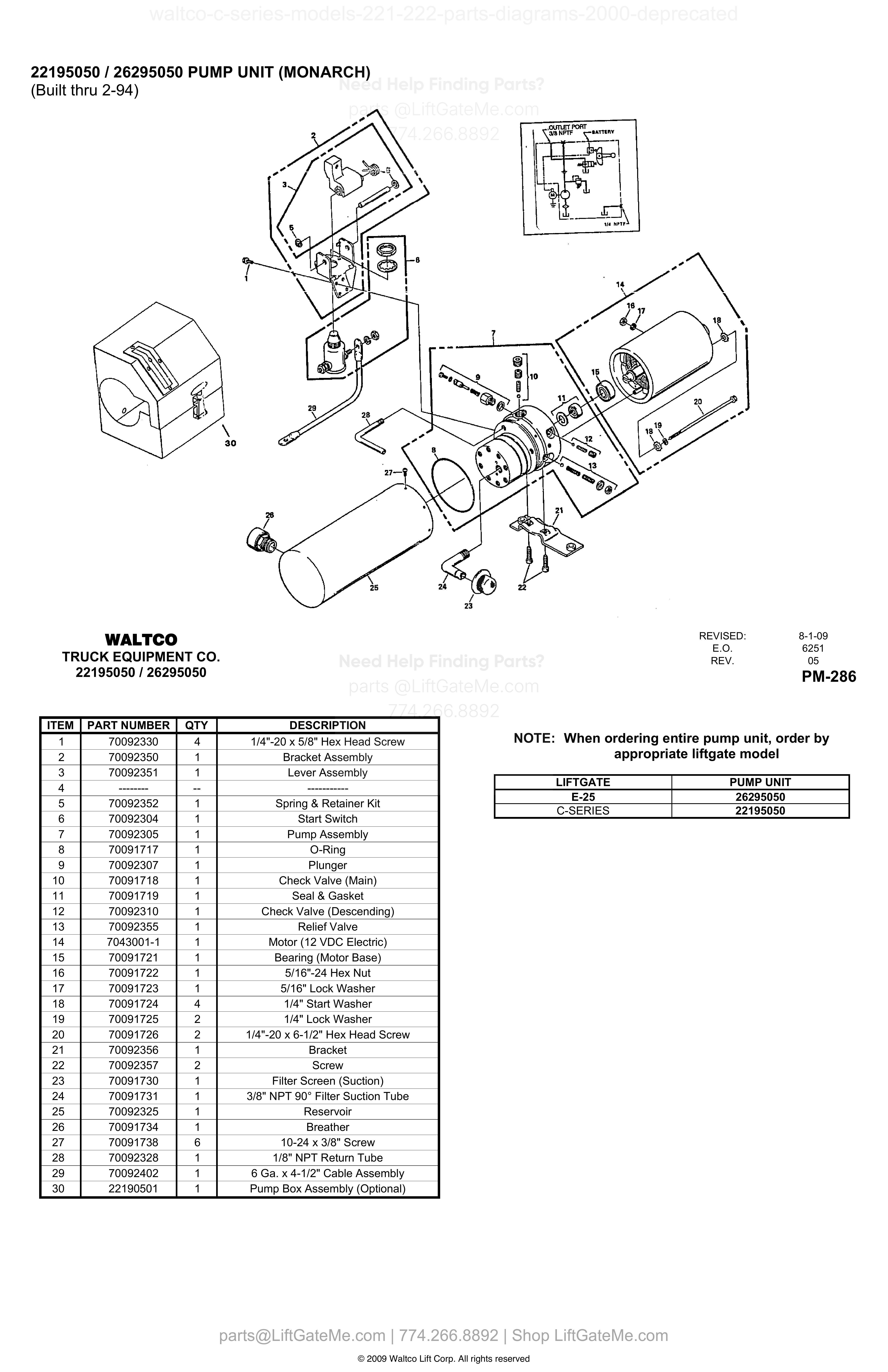
22195050 / 26295050 PUMP UNIT (MONARCH) (Built thru 2-94)
| Item | Qty | Part Number | Description | Actions |
|---|---|---|---|---|
| 1 | 4 | 70092330 | 1/4"-20 x 5/8" Hex Head Screw | |
| 2 | 1 | 70092350 | Bracket Assembly | |
| 3 | 1 | 70092351 | Lever Assembly | |
| 4 | -- | -------- | ----------- | |
| 5 | 1 | 70092352 | Spring & Retainer Kit | |
| 6 | 1 | 70092304 | Start Switch | |
| 7 | 1 | 70092305 | Pump Assembly | |
| 8 | 1 | 70091717 | O-Ring | |
| 9 | 1 | 70092307 | Plunger | |
| 10 | 1 | 70091718 | Check Valve (Main) | |
| 11 | 1 | 70091719 | Seal & Gasket | |
| 12 | 1 | 70092310 | Check Valve (Descending) | |
| 13 | 1 | 70092355 | Relief Valve | |
| 14 | 1 | 7043001-1 | Motor (12 VDC Electric) | |
| 15 | 1 | 70091721 | Bearing (Motor Base) | |
| 16 | 1 | 70091722 | 5/16"-24 Hex Nut | |
| 17 | 1 | 70091723 | 5/16" Lock Washer | |
| 18 | 4 | 70091724 | 1/4" Start Washer | |
| 19 | 2 | 70091725 | 1/4" Lock Washer | |
| 20 | 2 | 70091726 | 1/4"-20 x 6-1/2" Hex Head Screw | |
| 21 | 1 | 70092356 | Bracket | |
| 22 | 2 | 70092357 | Screw | |
| 23 | 1 | 70091730 | Filter Screen (Suction) | |
| 24 | 1 | 70091731 | 3/8" NPT 90° Filter Suction Tube | |
| 25 | 1 | 70092325 | Reservoir | |
| 26 | 1 | 70091734 | Breather | |
| 27 | 6 | 70091738 | 10-24 x 3/8" Screw | |
| 28 | 1 | 70092328 | 1/8" NPT Return Tube | |
| 29 | 1 | 70092402 | 6 Ga. x 4-1/2" Cable Assembly | |
| 30 | 1 | 22190501 | Pump Box Assembly (Optional) |
Reference Notice
Manual links are provided for reference only. If you have any doubt, contact us — we’re happy to verify parts and help you purchase with confidence.
Have your liftgate serial number ready for faster assistance. Where to find it
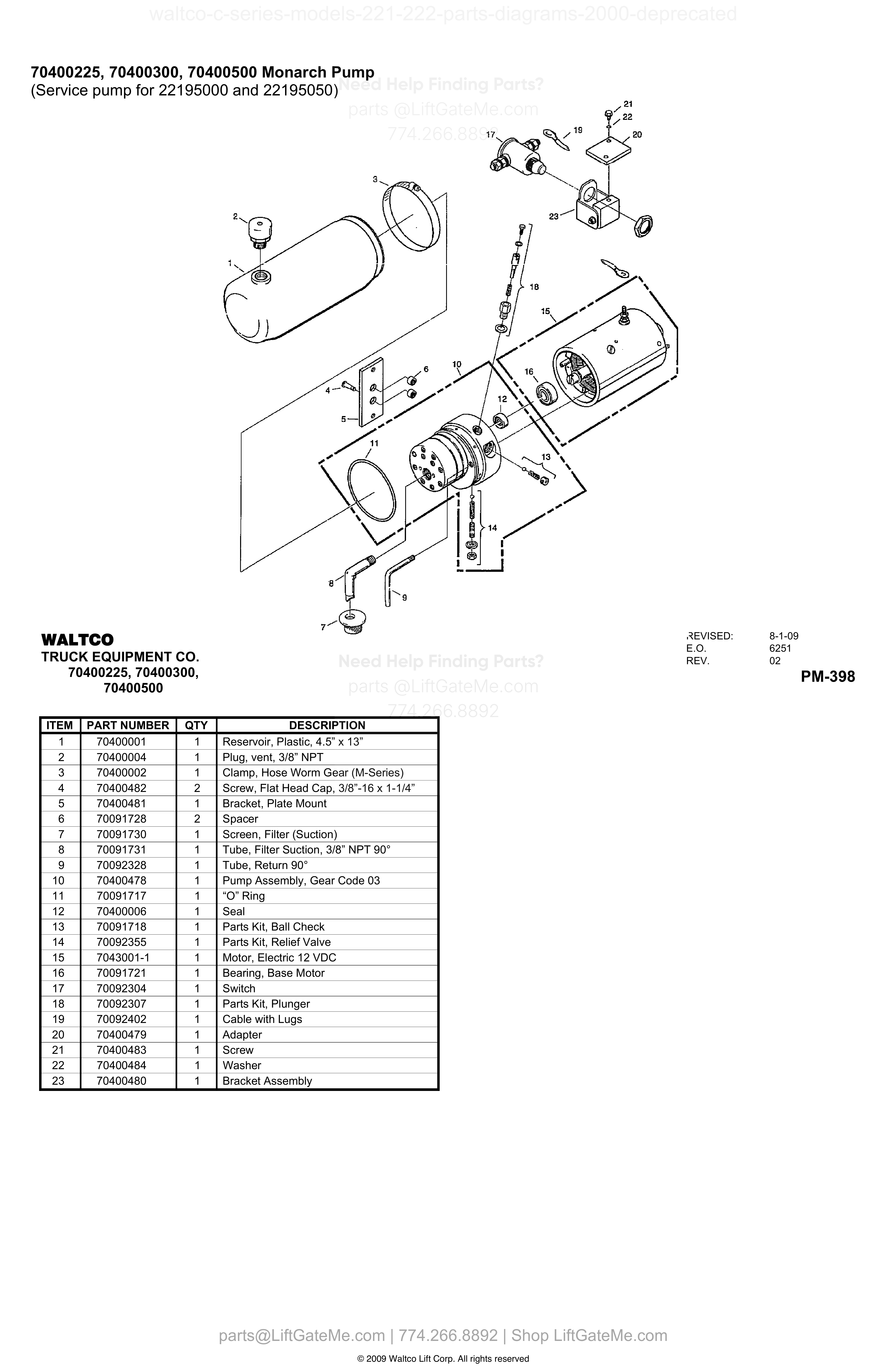
70400225, 70400300, 70400500 Monarch Pump
| Item | Qty | Part Number | Description | Actions |
|---|---|---|---|---|
| 1 | 1 | 70400001 | Reservoir, Plastic, 4.5” x 13” | |
| 2 | 1 | 70400004 | Plug, vent, 3/8” NPT | |
| 3 | 1 | 70400002 | Clamp, Hose Worm Gear (M-Series) | |
| 4 | 2 | 70400482 | Screw, Flat Head Cap, 3/8”-16 x 1-1/4” | |
| 5 | 1 | 70400481 | Bracket, Plate Mount | |
| 6 | 2 | 70091728 | Spacer | |
| 7 | 1 | 70091730 | Screen, Filter (Suction) | |
| 8 | 1 | 70091731 | Tube, Filter Suction, 3/8” NPT 90° | |
| 9 | 1 | 70092328 | Tube, Return 90° | |
| 10 | 1 | 70400478 | Pump Assembly, Gear Code 03 | |
| 11 | 1 | 70091717 | “O” Ring | |
| 12 | 1 | 70400006 | Seal | |
| 13 | 1 | 70091718 | Parts Kit, Ball Check | |
| 14 | 1 | 70092355 | Parts Kit, Relief Valve | |
| 15 | 1 | 7043001-1 | Motor, Electric 12 VDC | |
| 16 | 1 | 70091721 | Bearing, Base Motor | |
| 17 | 1 | 70092304 | Switch | |
| 18 | 1 | 70092307 | Parts Kit, Plunger | |
| 19 | 1 | 70092402 | Cable with Lugs | |
| 20 | 1 | 70400479 | Adapter | |
| 21 | 1 | 70400483 | Screw | |
| 22 | 1 | 70400484 | Washer | |
| 23 | 1 | 70400480 | Bracket Assembly |
SOLENOID OPERATED PUMP UNIT
| Item | Qty | Part Number | Description | Actions |
|---|---|---|---|---|
| 1 | 1 | U25163 | Motor | |
| 2 | 1 | 70091618 | Coupling | |
| 3 | 1 | 80001065 | Solenoid Kit | |
| 10 | 1 | 70091274 | End Head | |
| 11 | 2 | 70091291 | Plug | |
| 12 | 1 | 70091629 | Shaft Seal | |
| 20 | 1 | 70091615 | Pump Assembly Kit | |
| 29 | 1 | 70091758 | Suction Cover Kit | |
| 30 | 1 | 70091262 | Reservoir | |
| 31 | 4 | 70091265 | Screw | |
| 32 | 1 | 70091270 | Breather Cap | |
| 33 | 1 | 75000027 | “O” Ring | |
| 34 | 1 | 70091493 | Return Tube | |
| 40 | 1 | 70091249 | Ball | |
| 40 | 1 | 70091250 | Spring | |
| 41 | 1 | 70091295 | Check Cap Assembly | |
| 42 | 1 | 70091294 | Relief Cap Assembly | |
| 50 | 1 | 70091395 | Check Cap Assembly | |
| 52 | 1 | 70091696 | Spring Retainer | |
| 53 | 1 | 70091281 | Spring & Ball Assembly | |
| 59 | Valve Seal Kit | |||
| 59 | 1 | 75000025 | “O” Ring | |
| 59 | 2 | 75000026 | “O” Ring | |
| 59 | 2 | 75000036 | “O” Ring | |
| 59 | 2 | 70091297* | Seal Ring | |
| 61 | 1 | 80000722 | Release Cap Stem Assembly Kit | |
| 62 | 1 | 70091358* | Solenoid Bracket | |
| 63 | 6 | 70091352* | Screw | |
| 64 | 1 | 70091631 | Solenoid | |
| 65 | 1 | 70091353* | Cover |
Reference Notice
Manual links are provided for reference only. If you have any doubt, contact us — we’re happy to verify parts and help you purchase with confidence.
Have your liftgate serial number ready for faster assistance. Where to find it
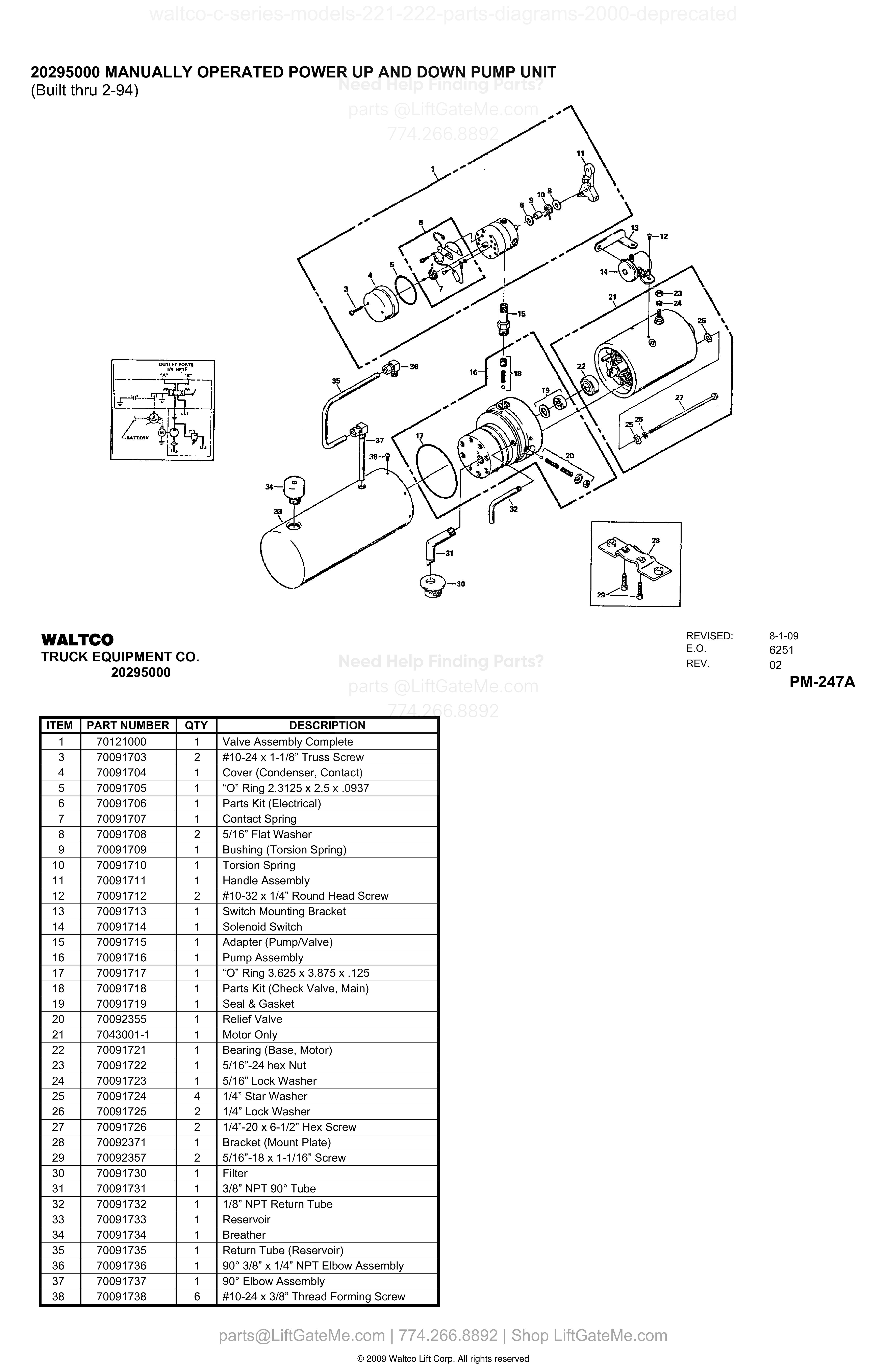
20295000 MANUALLY OPERATED POWER UP AND DOWN PUMP UNIT
| Item | Qty | Part Number | Description | Actions |
|---|---|---|---|---|
| 1 | 1 | 70121000 | Valve Assembly Complete | |
| 3 | 2 | 70091703 | #10-24 x 1-1/8” Truss Screw | |
| 4 | 1 | 70091704 | Cover (Condenser, Contact) | |
| 5 | 1 | 70091705 | “O” Ring 2.3125 x 2.5 x .0937 | |
| 6 | 1 | 70091706 | Parts Kit (Electrical) | |
| 7 | 1 | 70091707 | Contact Spring | |
| 8 | 2 | 70091708 | 5/16” Flat Washer | |
| 9 | 1 | 70091709 | Bushing (Torsion Spring) | |
| 10 | 1 | 70091710 | Torsion Spring | |
| 11 | 1 | 70091711 | Handle Assembly | |
| 12 | 2 | 70091712 | #10-32 x 1/4” Round Head Screw | |
| 13 | 1 | 70091713 | Switch Mounting Bracket | |
| 14 | 1 | 70091714 | Solenoid Switch | |
| 15 | 1 | 70091715 | Adapter (Pump/Valve) | |
| 16 | 1 | 70091716 | Pump Assembly | |
| 17 | 1 | 70091717 | “O” Ring 3.625 x 3.875 x .125 | |
| 18 | 1 | 70091718 | Parts Kit (Check Valve, Main) | |
| 19 | 1 | 70091719 | Seal & Gasket | |
| 20 | 1 | 70092355 | Relief Valve | |
| 21 | 1 | 7043001-1 | Motor Only | |
| 22 | 1 | 70091721 | Bearing (Base, Motor) | |
| 23 | 1 | 70091722 | 5/16”-24 hex Nut | |
| 24 | 1 | 70091723 | 5/16” Lock Washer | |
| 25 | 4 | 70091724 | 1/4” Star Washer | |
| 26 | 2 | 70091725 | 1/4” Lock Washer | |
| 27 | 2 | 70091726 | 1/4”-20 x 6-1/2” Hex Screw | |
| 28 | 1 | 70092371 | Bracket (Mount Plate) | |
| 29 | 2 | 70092357 | 5/16”-18 x 1-1/16” Screw | |
| 30 | 1 | 70091730 | Filter | |
| 31 | 1 | 70091731 | 3/8” NPT 90° Tube | |
| 32 | 1 | 70091732 | 1/8” NPT Return Tube | |
| 33 | 1 | 70091733 | Reservoir | |
| 34 | 1 | 70091734 | Breather | |
| 35 | 1 | 70091735 | Return Tube (Reservoir) | |
| 36 | 1 | 70091736 | 90° 3/8” x 1/4” NPT Elbow Assembly | |
| 37 | 1 | 70091737 | 90° Elbow Assembly | |
| 38 | 6 | 70091738 | #10-24 x 3/8” Thread Forming Screw |
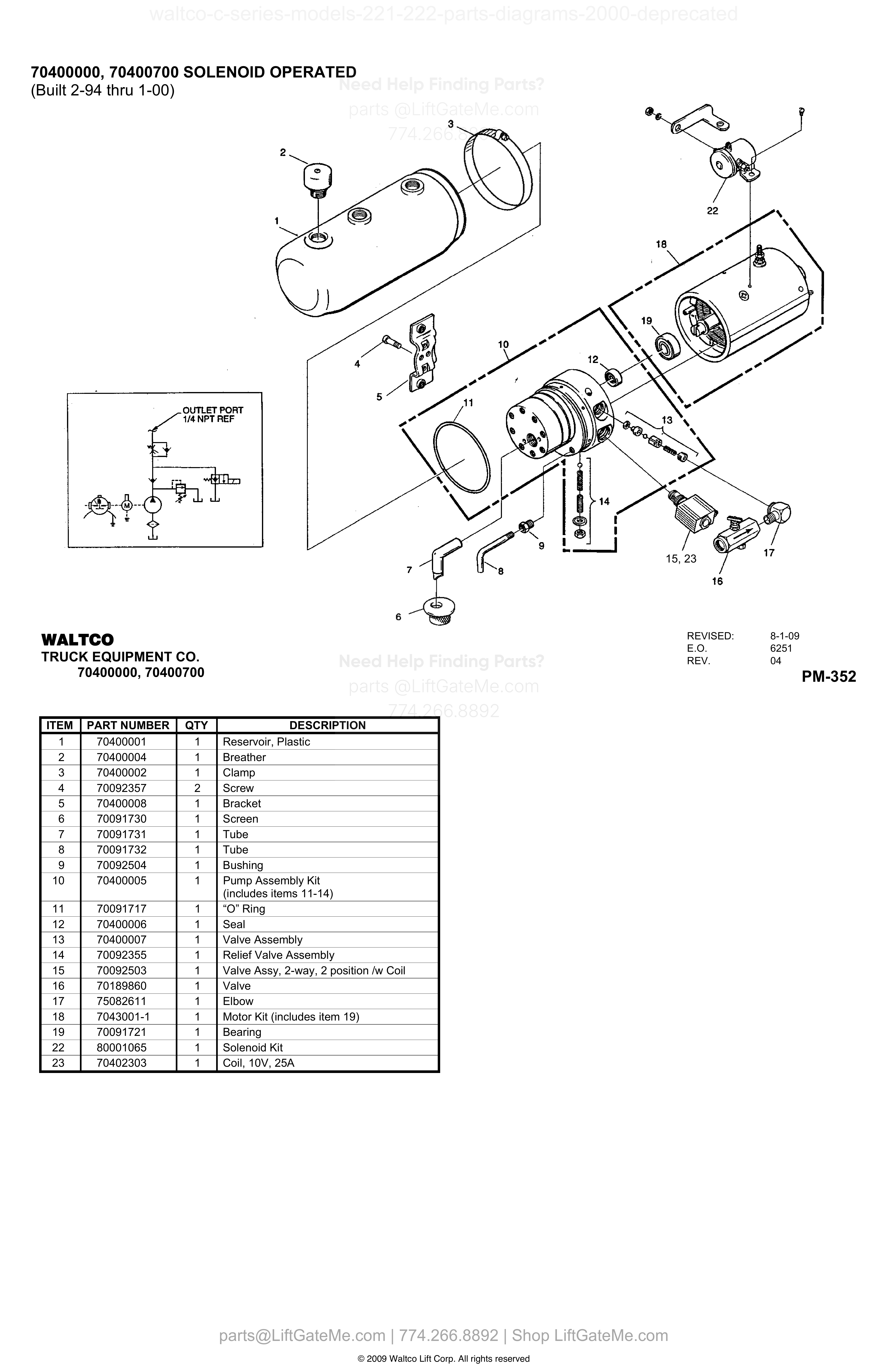
70400000, 70400700 SOLENOID OPERATED
| Item | Qty | Part Number | Description | Actions |
|---|---|---|---|---|
| 1 | 1 | 70400001 | Reservoir, Plastic | |
| 2 | 1 | 70400004 | Breather | |
| 3 | 1 | 70400002 | Clamp | |
| 4 | 2 | 70092357 | Screw | |
| 5 | 1 | 70400008 | Bracket | |
| 6 | 1 | 70091730 | Screen | |
| 7 | 1 | 70091731 | Tube | |
| 8 | 1 | 70091732 | Tube | |
| 9 | 1 | 70092504 | Bushing | |
| 10 | 1 | 70400005 | Pump Assembly Kit (includes items 11-14) | |
| 11 | 1 | 70091717 | “O” Ring | |
| 12 | 1 | 70400006 | Seal | |
| 13 | 1 | 70400007 | Valve Assembly | |
| 14 | 1 | 70092355 | Relief Valve Assembly | |
| 15 | 1 | 70092503 | Valve Assy, 2-way, 2 position /w Coil | |
| 16 | 1 | 70189860 | Valve | |
| 17 | 1 | 75082611 | Elbow | |
| 18 | 1 | 7043001-1 | Motor Kit (includes item 19) | |
| 19 | 1 | 70091721 | Bearing | |
| 22 | 1 | 80001065 | Solenoid Kit | |
| 23 | 1 | 70402303 | Coil, 10V, 25A |
Reference Notice
Manual links are provided for reference only. If you have any doubt, contact us — we’re happy to verify parts and help you purchase with confidence.
Have your liftgate serial number ready for faster assistance. Where to find it
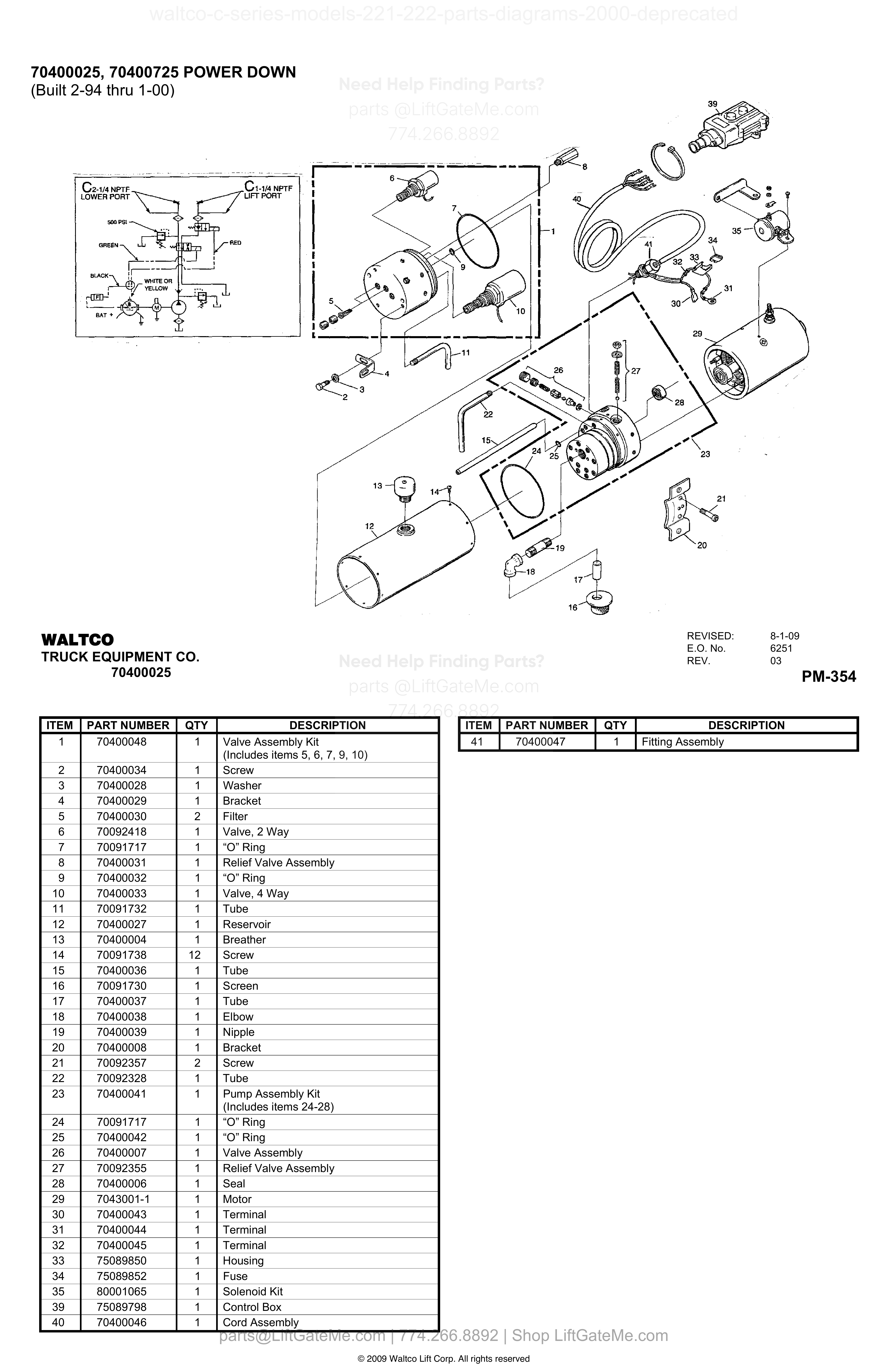
70400025, 70400725 POWER DOWN
| Item | Qty | Part Number | Description | Actions |
|---|---|---|---|---|
| 1 | 1 | 70400048 | Valve Assembly Kit (Includes items 5, 6, 7, 9, 10) | |
| 2 | 1 | 70400034 | Screw | |
| 3 | 1 | 70400028 | Washer | |
| 4 | 1 | 70400029 | Bracket | |
| 5 | 2 | 70400030 | Filter | |
| 6 | 1 | 70092418 | Valve, 2 Way | |
| 7 | 1 | 70091717 | “O” Ring | |
| 8 | 1 | 70400031 | Relief Valve Assembly | |
| 9 | 1 | 70400032 | “O” Ring | |
| 10 | 1 | 70400033 | Valve, 4 Way | |
| 11 | 1 | 70091732 | Tube | |
| 12 | 1 | 70400027 | Reservoir | |
| 13 | 1 | 70400004 | Breather | |
| 14 | 12 | 70091738 | Screw | |
| 15 | 1 | 70400036 | Tube | |
| 16 | 1 | 70091730 | Screen | |
| 17 | 1 | 70400037 | Tube | |
| 18 | 1 | 70400038 | Elbow | |
| 19 | 1 | 70400039 | Nipple | |
| 20 | 1 | 70400008 | Bracket | |
| 21 | 2 | 70092357 | Screw | |
| 22 | 1 | 70092328 | Tube | |
| 23 | 1 | 70400041 | Pump Assembly Kit (Includes items 24-28) | |
| 24 | 1 | 70091717 | “O” Ring | |
| 25 | 1 | 70400042 | “O” Ring | |
| 26 | 1 | 70400007 | Valve Assembly | |
| 27 | 1 | 70092355 | Relief Valve Assembly | |
| 28 | 1 | 70400006 | Seal | |
| 29 | 1 | 7043001-1 | Motor | |
| 30 | 1 | 70400043 | Terminal | |
| 31 | 1 | 70400044 | Terminal | |
| 32 | 1 | 70400045 | Terminal | |
| 33 | 1 | 75089850 | Housing | |
| 34 | 1 | 75089852 | Fuse | |
| 35 | 1 | 80001065 | Solenoid Kit | |
| 39 | 1 | 75089798 | Control Box | |
| 40 | 1 | 70400046 | Cord Assembly | |
| 41 | 1 | 70400047 | Fitting Assembly |
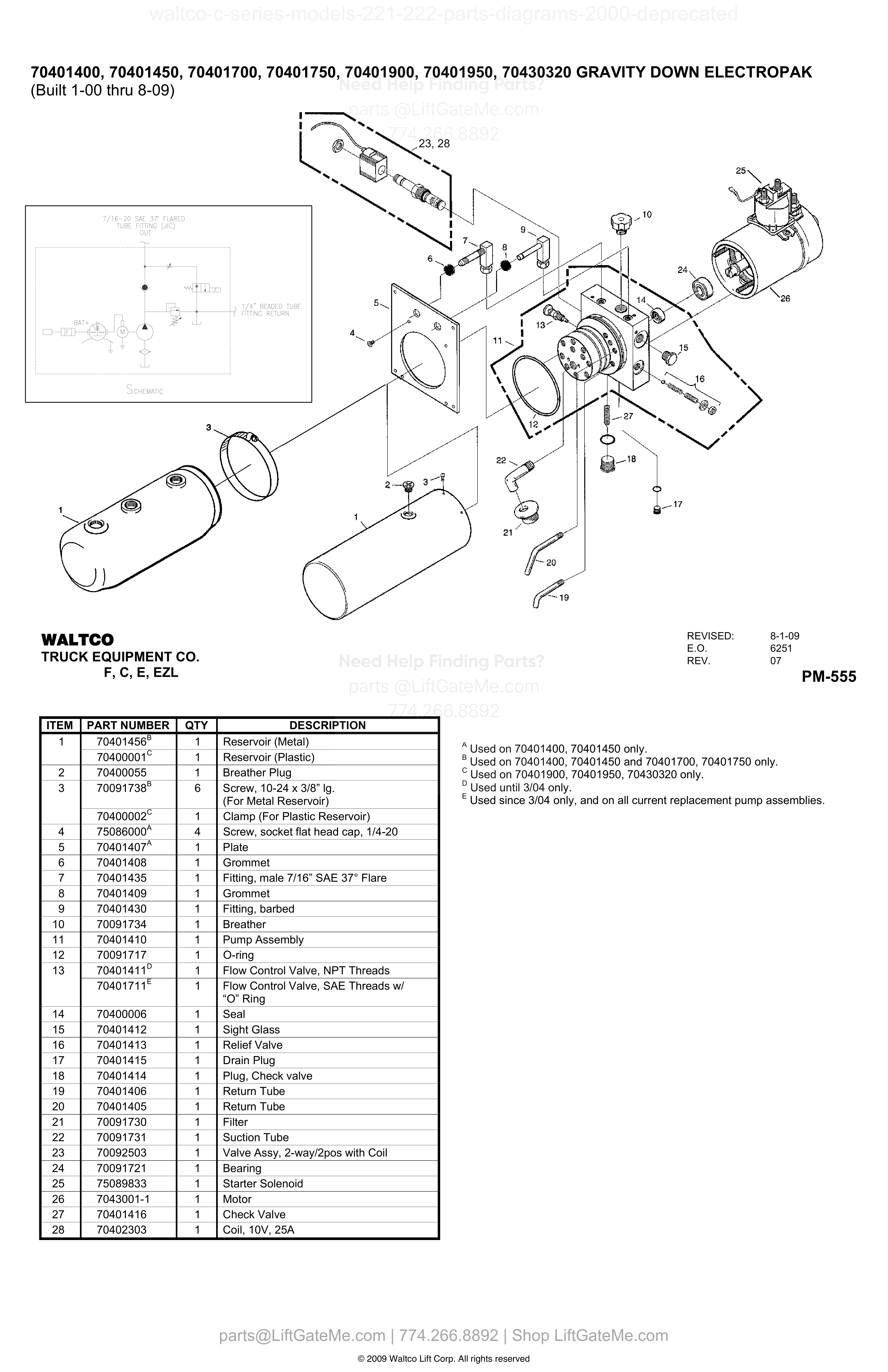
70401400, 70401450, 70401700, 70401750, 70401900, 70401950, 70430320 GRAVITY DOWN ELECTROPAK
| Item | Qty | Part Number | Description | Actions |
|---|---|---|---|---|
| 1 | 1 | 70401456 B | Reservoir (Metal) | |
| 1 | 1 | 70400001 C | Reservoir (Plastic) | |
| 2 | 1 | 70400055 | Breather Plug | |
| 3 | 6 | 70091738 B | Screw, 10-24 x 3/8” lg. (For Metal Reservoir) | |
| 3 | 1 | 70400002 C | Clamp (For Plastic Reservoir) | |
| 4 | 4 | 75086000 A | Screw, socket flat head cap, 1/4-20 | |
| 5 | 1 | 70401407 A | Plate | |
| 6 | 1 | 70401408 | Grommet | |
| 7 | 1 | 70401435 | Fitting, male 7/16” SAE 37° Flare | |
| 8 | 1 | 70401409 | Grommet | |
| 9 | 1 | 70401430 | Fitting, barbed | |
| 10 | 1 | 70091734 | Breather | |
| 11 | 1 | 70401410 | Pump Assembly | |
| 12 | 1 | 70091717 | O-ring | |
| 13 | 1 | 70401411 D | Flow Control Valve, NPT Threads | |
| 13 | 1 | 70401711 E | Flow Control Valve, SAE Threads w/ “O” Ring | |
| 14 | 1 | 70400006 | Seal | |
| 15 | 1 | 70401412 | Sight Glass | |
| 16 | 1 | 70401413 | Relief Valve | |
| 17 | 1 | 70401415 | Drain Plug | |
| 18 | 1 | 70401414 | Plug, Check valve | |
| 19 | 1 | 70401406 | Return Tube | |
| 20 | 1 | 70401405 | Return Tube | |
| 21 | 1 | 70091730 | Filter | |
| 22 | 1 | 70091731 | Suction Tube | |
| 23 | 1 | 70092503 | Valve Assy, 2-way/2pos with Coil | |
| 24 | 1 | 70091721 | Bearing | |
| 25 | 1 | 75089833 | Starter Solenoid | |
| 26 | 1 | 7043001-1 | Motor | |
| 27 | 1 | 70401416 | Check Valve | |
| 28 | 1 | 70402303 | Coil, 10V, 25A |
Reference Notice
Manual links are provided for reference only. If you have any doubt, contact us — we’re happy to verify parts and help you purchase with confidence.
Have your liftgate serial number ready for faster assistance. Where to find it
70401425, 70401475, 70401725, 70401775, 70401925, 70401975, 70430430 POWER DOWN
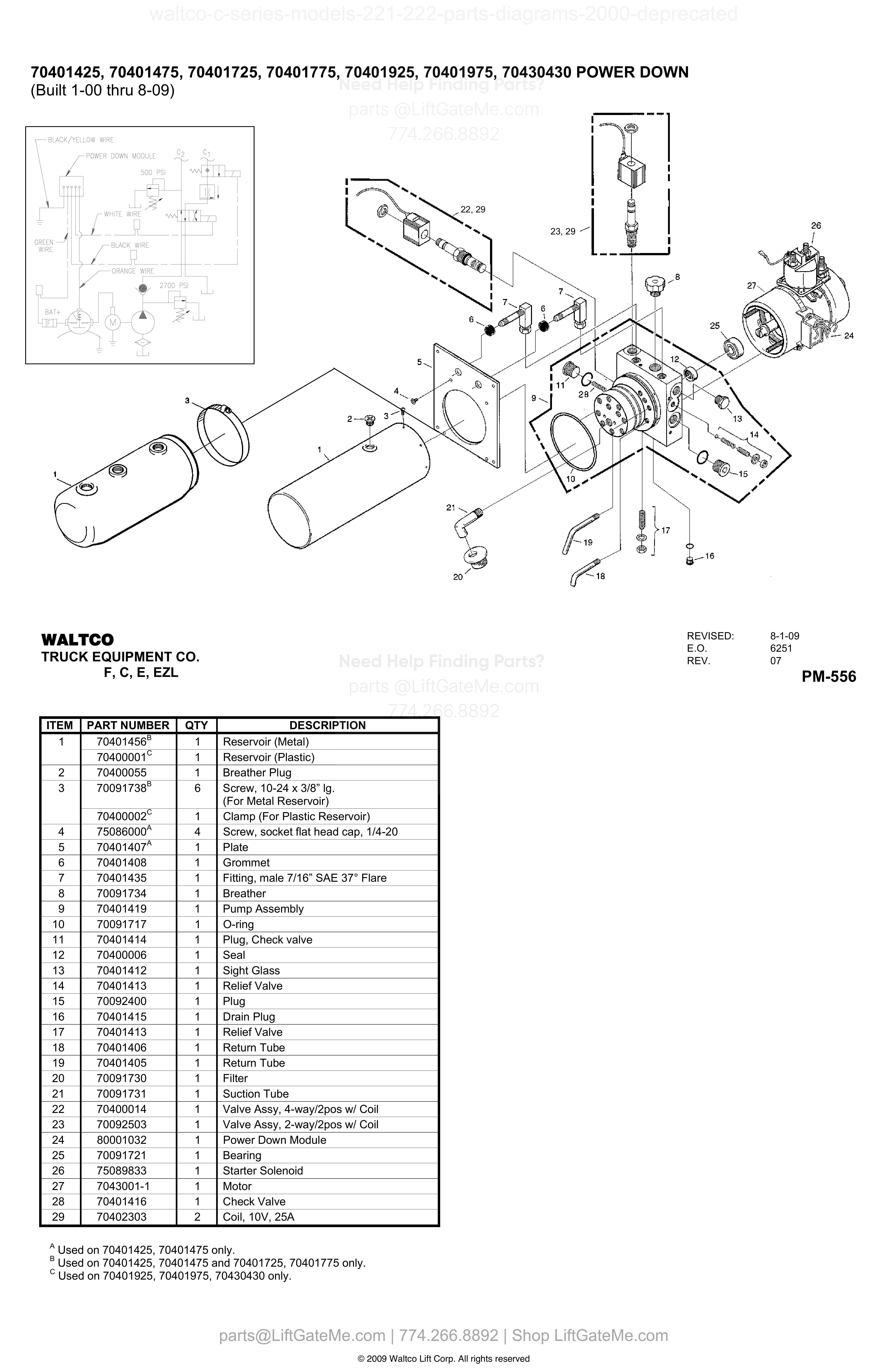
| Item | Qty | Part Number | Description | Actions |
|---|---|---|---|---|
| 1 | 1 | 70401456 B | Reservoir (Metal) | |
| 1 | 1 | 70400001 C | Reservoir (Plastic) | |
| 2 | 1 | 70400055 | Breather Plug | |
| 3 | 6 | 70091738 B | Screw, 10-24 x 3/8” lg. (For Metal Reservoir) | |
| 3 | 1 | 70400002 C | Clamp (For Plastic Reservoir) | |
| 4 | 4 | 75086000 A | Screw, socket flat head cap, 1/4-20 | |
| 5 | 1 | 70401407 A | Plate | |
| 6 | 1 | 70401408 | Grommet | |
| 7 | 1 | 70401435 | Fitting, male 7/16” SAE 37° Flare | |
| 8 | 1 | 70091734 | Breather | |
| 9 | 1 | 70401419 | Pump Assembly | |
| 10 | 1 | 70091717 | O-ring | |
| 11 | 1 | 70401414 | Plug, Check valve | |
| 12 | 1 | 70400006 | Seal | |
| 13 | 1 | 70401412 | Sight Glass | |
| 14 | 1 | 70401413 | Relief Valve | |
| 15 | 1 | 70092400 | Plug | |
| 16 | 1 | 70401415 | Drain Plug | |
| 17 | 1 | 70401413 | Relief Valve | |
| 18 | 1 | 70401406 | Return Tube | |
| 19 | 1 | 70401405 | Return Tube | |
| 20 | 1 | 70091730 | Filter | |
| 21 | 1 | 70091731 | Suction Tube | |
| 22 | 1 | 70400014 | Valve Assy, 4-way/2pos w/ Coil | |
| 23 | 1 | 70092503 | Valve Assy, 2-way/2pos w/ Coil | |
| 24 | 1 | 80001032 | Power Down Module | |
| 25 | 1 | 70091721 | Bearing | |
| 26 | 1 | 75089833 | Starter Solenoid | |
| 27 | 1 | 7043001-1 | Motor | |
| 28 | 1 | 70401416 | Check Valve | |
| 29 | 2 | 70402303 | Coil, 10V, 25A |
22180050
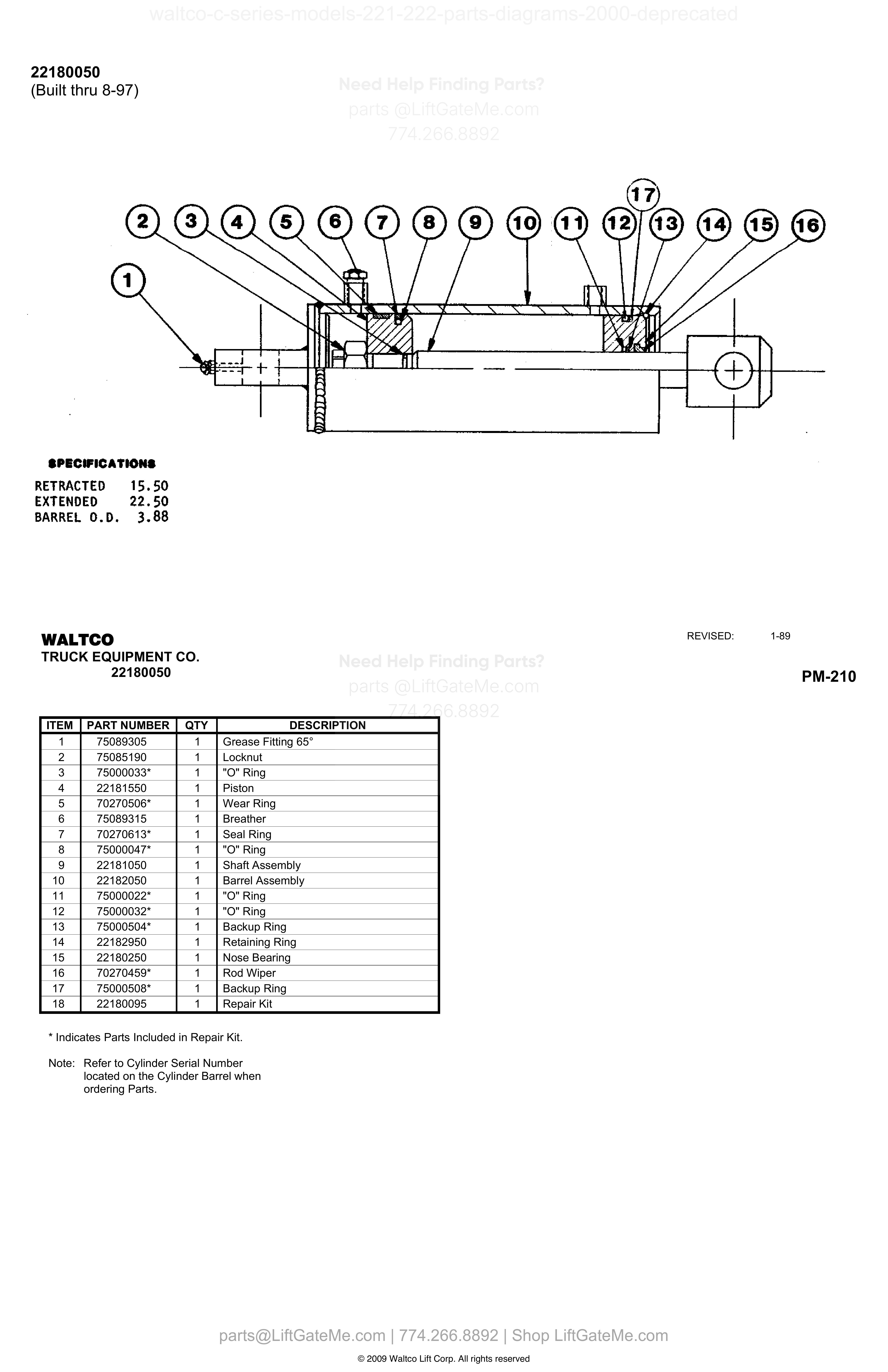
| Item | Qty | Part Number | Description | Actions |
|---|---|---|---|---|
| 1 | 1 | 75089305 | Grease Fitting 65° | |
| 2 | 1 | 75085190 | Locknut | |
| 3 | 1 | 75000033* | "O" Ring | |
| 4 | 1 | 22181550 | Piston | |
| 5 | 1 | 70270506* | Wear Ring | |
| 6 | 1 | 75089315 | Breather | |
| 7 | 1 | 70270613* | Seal Ring | |
| 8 | 1 | 75000047* | "O" Ring | |
| 9 | 1 | 22181050 | Shaft Assembly | |
| 10 | 1 | 22182050 | Barrel Assembly | |
| 11 | 1 | 75000022* | "O" Ring | |
| 12 | 1 | 75000032* | "O" Ring | |
| 13 | 1 | 75000504* | Backup Ring | |
| 14 | 1 | 22182950 | Retaining Ring | |
| 15 | 1 | 22180250 | Nose Bearing | |
| 16 | 1 | 70270459* | Rod Wiper | |
| 17 | 1 | 75000508* | Backup Ring | |
| 18 | 1 | 22180095 | Repair Kit |
Reference Notice
Manual links are provided for reference only. If you have any doubt, contact us — we’re happy to verify parts and help you purchase with confidence.
Have your liftgate serial number ready for faster assistance. Where to find it
22280050
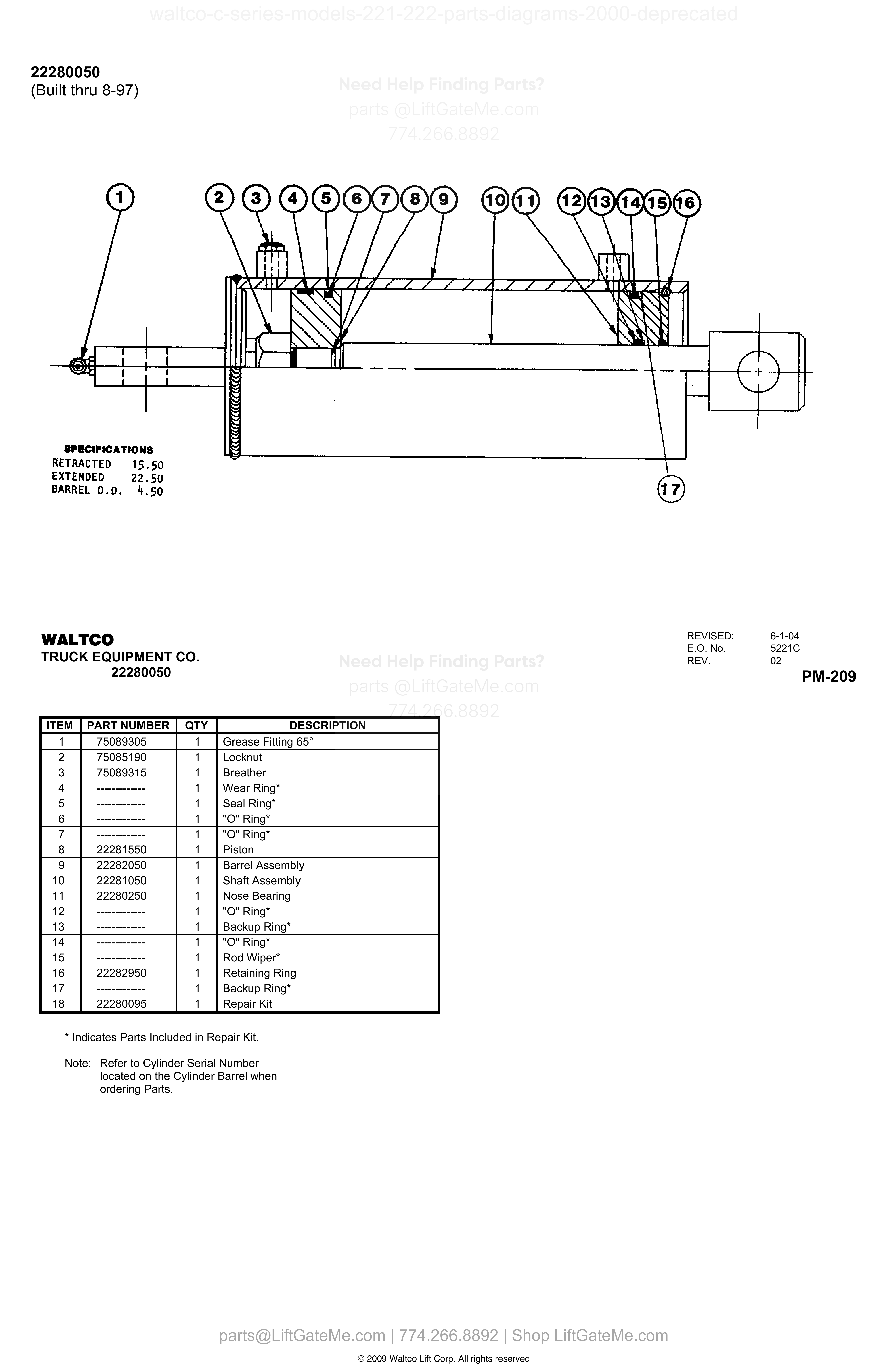
| Item | Qty | Part Number | Description | Actions |
|---|---|---|---|---|
| 1 | 1 | 75089305 | Grease Fitting 65° | |
| 2 | 1 | 75085190 | Locknut | |
| 3 | 1 | 75089315 | Breather | |
| 4 | 1 | ------------- | Wear Ring* | |
| 5 | 1 | ------------- | Seal Ring* | |
| 6 | 1 | ------------- | "O" Ring* | |
| 7 | 1 | ------------- | "O" Ring* | |
| 8 | 1 | 22281550 | Piston | |
| 9 | 1 | 22282050 | Barrel Assembly | |
| 10 | 1 | 22281050 | Shaft Assembly | |
| 11 | 1 | 22280250 | Nose Bearing | |
| 12 | 1 | ------------- | "O" Ring* | |
| 13 | 1 | ------------- | Backup Ring* | |
| 14 | 1 | ------------- | "O" Ring* | |
| 15 | 1 | ------------- | Rod Wiper* | |
| 16 | 1 | 22282950 | Retaining Ring | |
| 17 | 1 | ------------- | Backup Ring* | |
| 18 | 1 | 22280095 | Repair Kit |
22180010 (Built from 8-97)
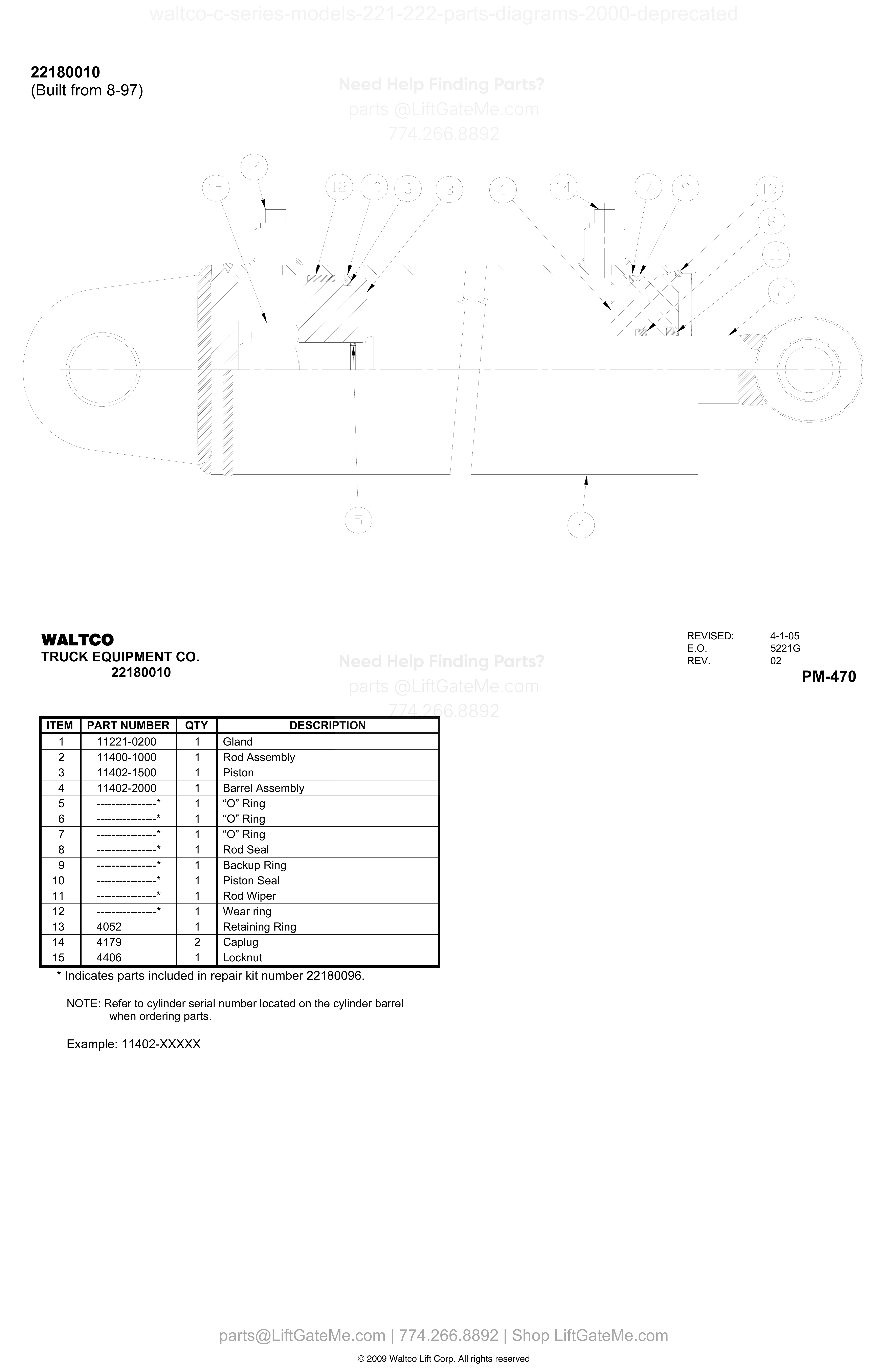
| Item | Qty | Part Number | Description | Actions |
|---|---|---|---|---|
| 1 | 1 | 11221-0200 | Gland | |
| 2 | 1 | 11400-1000 | Rod Assembly | |
| 3 | 1 | 11402-1500 | Piston | |
| 4 | 1 | 11402-2000 | Barrel Assembly | |
| 5 | 1 | ----------------* | “O” Ring | |
| 6 | 1 | ----------------* | “O” Ring | |
| 7 | 1 | ----------------* | “O” Ring | |
| 8 | 1 | ----------------* | Rod Seal | |
| 9 | 1 | ----------------* | Backup Ring | |
| 10 | 1 | ----------------* | Piston Seal | |
| 11 | 1 | ----------------* | Rod Wiper | |
| 12 | 1 | ----------------* | Wear ring | |
| 13 | 1 | 4052 | Retaining Ring | |
| 14 | 2 | 4179 | Caplug | |
| 15 | 1 | 4406 | Locknut |
Reference Notice
Manual links are provided for reference only. If you have any doubt, contact us — we’re happy to verify parts and help you purchase with confidence.
Have your liftgate serial number ready for faster assistance. Where to find it
22280010

| Item | Qty | Part Number | Description | Actions |
|---|---|---|---|---|
| 1 | 1 | 11222-0200 | Gland | |
| 2 | 1 | 11400-1000 | Rod Assembly | |
| 3 | 1 | 11400-1500 | Piston | |
| 4 | 1 | 11400-2000 | Barrel Assembly | |
| 5 | 1 | ----------------* | “O” Ring | |
| 6 | 1 | ----------------* | “O” Ring | |
| 7 | 1 | ----------------* | “O” Ring | |
| 8 | 1 | ----------------* | Rod Seal | |
| 9 | 1 | ----------------* | Backup Ring | |
| 10 | 1 | ----------------* | Piston Seal | |
| 11 | 1 | ----------------* | Rod Wiper | |
| 12 | 1 | ----------------* | Wear ring | |
| 13 | 1 | 4050 | Retaining Ring | |
| 14 | 2 | 4179 | Caplug | |
| 15 | 1 | 4406 | Locknut |
22280010
| Item | Qty | Part Number | Description | Actions |
|---|---|---|---|---|
| 1 | 1 | 11222-0200 | Gland | |
| 2 | 1 | 11400-1000 | Rod Assembly | |
| 3 | 1 | 11400-1500 | Piston | |
| 4 | 1 | 11400-2000 | Barrel Assembly | |
| 5 | 1 | ---------------- * | “O” Ring | |
| 6 | 1 | ---------------- * | “O” Ring | |
| 7 | 1 | ---------------- * | “O” Ring | |
| 8 | 1 | ---------------- * | Rod Seal | |
| 9 | 1 | ---------------- * | Backup Ring | |
| 10 | 1 | ---------------- * | Piston Seal | |
| 11 | 1 | ---------------- * | Rod Wiper | |
| 12 | 1 | ---------------- * | Wear ring | |
| 13 | 1 | 4050 | Retaining Ring | |
| 14 | 2 | 4179 | Caplug | |
| 15 | 1 | 4406 | Locknut |
Need help confirming the correct part?
Share model, serial, and item number.
Fast technical support
Use this after reviewing the diagram and table. We can verify compatibility before purchase.
Phone
(774) 266-8892Send your details and we will help identify the right replacement part.
Contact SupportImportant Diagram Notice
These diagrams are for reference only.
- Due to unintended occasional data alignment issues, a page table may differ slightly from the original OEM PDF.
- Please verify details against the original PDF file.
- Contact our team anytime for part number confirmation.
Reference mismatch detected