
Changing BZ Circuit Boards
CHANGING BZ CIRCUIT BOARDS
This new circuit board (p/n Z34301TL) is designed to replace most circuit boards used on BZ liftgates.
It will replace these type of boards:

It will not replace circuit boards of these designs:

Note: If your circuit board does not look like any of
the above, contact us at 774.266.3297
Circuit Board Kit 80002247:
Contains:
• 1 pc Circuit Board (p/n Z34301TL)
• 2 pc Blue wires
• 2 pc Yellow wires
• 2 pc Green wires
• 6 pc White wires
• 2 pc Black wires
• 2 pc Orange wires
• 16 pcs Heat Shrink Connectors
• 1 pc Decal
• 1 pc 12” Green jumper wire (10098431)
• 1 pc These Installation Instructions (80101710)
• 1 pc Set of wire labels (80101711)
Board for two (2)
wire switches
Small board
with relays
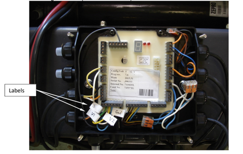
1. Remove protective cover by unscrewing plastic nuts.

2. Determine this kit will replace the circuit board on your liftgate. Your circuit board is similar to one of the two pictured at top of first page.
3. Disable liftgate by disconnecting batteries to liftgate.
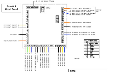
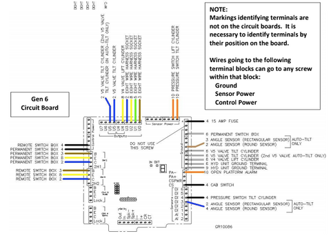
4. Before unscrewing wires from terminal blocks, install a label, corresponding to terminal designation, on each wire. Follow drawings on page 3 to install labels according to type of circuit board being removed (Gen 4/5 or Gen 6).
5. Remove wires from terminals, then remove the old circuit board, board is held in place with three (3) screws.
6. Attach new circuit board with same three screws.
7. Connect wires to new circuit board.
If replacing Gen 4/Gen 5 Circuit Board with a Gen 6 Board, refer to chart below
and diagrams above to determine corresponding terminals.

* Gen 6 liftgates with Auto-Tilt may have additional Blue (2) wire run to
second U5 terminal, as well as additional White (6) wire run to Ground
8. Install 12” green jumper wire, supplied in kit, between “sensor power” and Di2 terminals.
Note: Angle sensor is located on lift arm.

Rectangular Angle Sensor
Round Angle Sensor
Note: If liftgate is not equipped with cab shut-off switch, or switch on the trailer to
cut electrical power to control switches, you will have to use a jumper wire
on the circuit board. Jump between Control Power and Cs terminals.
On old Gen 4/5 boards a jumper may have been used between Cs and the
+ terminal next to it.
Note: Some wires may have to be extended. Before you extend the wire, try
loosening the strain relief nut and pulling on wire to see if it will extend.
If necessary, use wires provided in kit to extend wires to properly reach circuit board.

9. Change decal (supplied with kit) inside protective cover.
10. Reinstall protective cover, making sure it properly seals.
11. Reconnect battery power to liftgate and test all functions of liftgate.


0 comments